Arduino: what can be done with it. Arduino for beginners: step-by-step instructions. Arduino Programming and Projects: Where to Start? Arduino designs
In this article I decided to collect a complete step by step guide for Arduino beginners. We will look at what Arduino is, what you need to start learning, where to download and how to install and configure the programming environment, how it works and how to use the programming language, and much more that is necessary to create full-fledged complex devices based on the family of these microcontrollers.
Here I will try to give a condensed minimum so that you understand the principles of working with Arduino. For a more complete immersion in the world of programmable microcontrollers, pay attention to other sections and articles of this site. I will leave links to other materials on this site for a more detailed study of some aspects.
What is Arduino and what is it for?
Arduino is an electronic construction kit that allows anyone to create a variety of electro-mechanical devices. Arduino consists of software and hardware. The software part includes a development environment (a program for writing and debugging firmware), many ready-made and convenient libraries, and a simplified programming language. The hardware includes a large line of microcontrollers and ready-made modules for them. Thanks to this, working with Arduino is very easy!
With the help of Arduino you can learn programming, electrical engineering and mechanics. But this is not just an educational constructor. Based on it, you can make really useful devices.
Starting from simple flashing lights, weather stations, automation systems and ending with smart home systems, CNC machines and unmanned aerial vehicles. The possibilities are not even limited by your imagination, because there are a huge number of instructions and ideas for implementation.
Arduino Starter Kit
In order to start learning Arduino, you need to acquire the microcontroller board itself and additional parts. It is best to purchase an Arduino starter kit, but you can choose everything you need yourself. I recommend choosing a set because it's easier and often cheaper. Here are links to the best sets and individual parts that you will definitely need to study:
| Basic Arduino kit for beginners: | Buy |
| Large set for training and first projects: | Buy |
| Set of additional sensors and modules: | Buy |
| Arduino Uno is the most basic and convenient model from the line: | Buy |
| Solderless breadboard for easy learning and prototyping: | Buy |
| Set of wires with convenient connectors: | Buy |
| LED set: | Buy |
| Resistor kit: | Buy |
| Buttons: | Buy |
| Potentiometers: | Buy |
Arduino IDE development environment
To write, debug and download firmware, you need to download and install the Arduino IDE. This is a very simple and convenient program. On my website I have already described the process of downloading, installing and configuring the development environment. So here I will just leave links to latest version programs and
| Version | Windows | Mac OS X | Linux |
| 1.8.2 |
Arduino programming language
When you have a microcontroller board in your hands and a development environment installed on your computer, you can start writing your first sketches (firmware). To do this, you need to become familiar with the programming language.
Arduino programming uses a simplified version of the C++ language with predefined functions. As in other C-like programming languages, there are a number of rules for writing code. Here are the most basic ones:
- Each instruction must be followed by a semicolon (;)
- Before declaring a function, you must specify the data type returned by the function, or void if the function does not return a value.
- It is also necessary to indicate the data type before declaring a variable.
- Comments are designated: // Inline and /* block */
You can learn more about data types, functions, variables, operators and language constructs on the page on You do not need to memorize and remember all this information. You can always go to the reference book and look at the syntax of a particular function.
All Arduino firmware must contain at least 2 functions. These are setup() and loop().
setup function
In order for everything to work, we need to write a sketch. Let's make the LED light up after pressing the button, and go out after the next press. Here's our first sketch:
// variables with pins of connected devices int switchPin = 8; int ledPin = 11; // variables to store the state of the button and LED boolean lastButton = LOW; boolean currentButton = LOW; boolean ledOn = false; void setup() ( pinMode(switchPin, INPUT); pinMode(ledPin, OUTPUT); ) // function for debouncing boolean debounse(boolean last) ( boolean current = digitalRead(switchPin); if(last != current) ( delay (5); current = digitalRead(switchPin); ) return current; ) void loop() ( currentButton = debounse(lastButton); if(lastButton == LOW && currentButton == HIGH) ( ledOn = !ledOn; ) lastButton = currentButton ; digitalWrite(ledPin, ledOn); )
// variables with pins of connected devices int switchPin = 8 ; int ledPin = 11 ; // variables to store the state of the button and LED boolean lastButton = LOW ; boolean currentButton = LOW ; boolean ledOn = false ; void setup() ( pinMode(switchPin, INPUT); pinMode(ledPin, OUTPUT); // function for debouncing boolean debounse (boolean last ) ( boolean current = digitalRead(switchPin); if (last != current ) ( delay(5); current = digitalRead(switchPin); return current ; void loop() ( currentButton = debounse(lastButton); if (lastButton == LOW && currentButton == HIGH ) ( ledOn = ! ledOn; lastButton = currentButton ; digitalWrite(ledPin, ledOn); |
In this sketch, I created an additional debounse function to suppress contact bounce. There is information about contact bounce on my website. Be sure to check out this material.
PWM Arduino
Pulse width modulation (PWM) is the process of controlling voltage using the duty cycle of a signal. That is, using PWM we can smoothly control the load. For example, you can smoothly change the brightness of an LED, but this change in brightness is obtained not by decreasing the voltage, but by increasing the intervals of the low signal. The operating principle of PWM is shown in this diagram:

When we apply PWM to the LED, it starts to quickly light up and go out. The human eye is not able to see this because the frequency is too high. But when shooting video, you will most likely see moments when the LED is not lit. This will happen provided that the camera frame rate is not a multiple of the PWM frequency.
Arduino has a built-in pulse width modulator. You can use PWM only on those pins that are supported by the microcontroller. For example, Arduino Uno and Nano have 6 PWM pins: these are pins D3, D5, D6, D9, D10 and D11. The pins may differ on other boards. You can find a description of the board you are interested in in
To use PWM in Arduino there is a function. It takes as arguments the pin number and the PWM value from 0 to 255. 0 is 0% fill with a high signal, and 255 is 100%. Let's write a simple sketch as an example. Let's make the LED light up smoothly, wait one second and fade out just as smoothly, and so on ad infinitum. Here is an example of using this function:
// The LED is connected to pin 11 int ledPin = 11; void setup() ( pinMode(ledPin, OUTPUT); ) void loop() ( for (int i = 0; i< 255; i++) { analogWrite(ledPin, i); delay(5); } delay(1000); for (int i = 255; i >0; i--) ( analogWrite(ledPin, i); delay(5); ) )
// LED connected to pin 11 int ledPin = 11 ; void setup() ( pinMode(ledPin, OUTPUT); void loop() ( for (int i = 0 ; i< 255 ; i ++ ) { analogWrite(ledPin, i); delay(5); delay(1000); for (int i = 255; i > 0; i -- ) ( |
A series of articles and training diagrams with amateur radio experiments on Arduino for beginners. This is such an amateur radio construction toy, from which, without a soldering iron, etching of printed circuit boards and the like, any electronics kettle can assemble a full-fledged working device, suitable for both professional prototyping and amateur experiments in the study of electronics.
The Arduino board is intended primarily for teaching novice radio amateurs the basics of programming microcontrollers and creating microcontroller devices with their own hands without serious theoretical training. The Arduino development environment allows you to compile and load ready-made program code into the board memory. Moreover, loading the code is extremely simple.
Arduino where to start for a beginner |
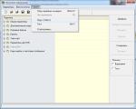
First of all, to work with the Arduino board, a novice electronics engineer needs to download the Arduino development program; it consists of a built-in text editor in which we work with program code, a message area, a text output window (console), a toolbar with buttons for frequently used commands and several menus. To download its programs and communicate, this program is connected to the Arduino board via a standard USB cable.

Code written in the Arduino environment is called sketch. It is written in text editor, which has special tools for inserting/cutting, replacing/searching text. During saving and exporting, explanations appear in the message area (see the picture in the first lesson for beginners, just below), and errors may also be displayed. The console displays Arduino messages, including full error reports and other useful information. Toolbar buttons allow you to check and record a sketch, open, create and save it, open serial bus monitoring, and much more.
So, let's move on to the first lesson of Arduino circuits for beginner electronics engineers.
For the convenience of beginners, the Arduino UNO controller already has a resistance and an LED connected to pin 13 of the connector, so we don’t need any external radio elements in the first experiment.

By loading the code, Arduino allows our program to participate in system initialization. To do this, we indicate to the microcontroller commands that it will execute at the time of initial boot and then completely forget about them (i.e., these commands will be executed by the Arduino only once at startup). And it is for this purpose that in our code we select a block in which these commands are stored. void setup(), or rather in the space inside the curly braces of this function, see the program sketch.
Don't forget about braces! The loss of at least one of them will make the entire sketch completely unworkable. But don’t put extra parentheses either, as this will also cause an error.
| Download code:
|

Function void loop() this is where we put the commands that will be executed as long as the Arduino is turned on. Having started execution from the first command, the Arduino will reach the very end and immediately go to the beginning to repeat the same sequence. And so on an infinite number of times, as long as the board receives power. At its core, a void loop is the main function, the entry point into Arduino.
Function delay(1000) delays program processing by 1000 milliseconds. It all goes on in an eternal cycle loop().
The main conclusion after understanding our first program on Arduino: Using the void loop and void setup functions, we pass our instructions to the microcontroller. Everything that is inside the setup block will be executed only once. The contents of the loop module will be repeated in a loop as long as the Arduino remains turned on.
In the previous program there was a second delay between turning the LED on and off. There was one big minus in the simplest code of a novice Arduino operator used above. To maintain a pause between turning on and off the LED for one second, we used the function delay() and therefore at this moment the controller is not able to execute other commands in the main function loop(). Correcting code in a function loop(), presented below solves this problem.
Instead of setting the value to HIGH and then to LOW, we will get the value of ledPin and invert it. Let’s say if it was HIGH, it will become LOW, etc.

Second Arduino code option for LED control Here:
Then you can replace the function delay(). Instead, it is better to use the function millis(). It returns the number of milliseconds that have passed since the program started. The function will overflow after approximately 50 days of running the program code.
A similar function is micros(), which returns the number of microseconds that have passed since the program code was launched. The function will return to zero after 70 minutes of program operation.
Of course, this will add a few lines of code to our sketch, but it will undoubtedly make you a more experienced programmer and increase the potential of your Arduino. To do this, you just need to learn how to use the millis function.
It should be clearly understood that the simplest delay function pauses the execution of the entire Arduino program, making it unable to perform any tasks during this period of time. Instead of pausing our entire program, we can count how much time has passed before the action completes. This, nicely, is implemented using the millis() function. To make everything easy to understand, we will consider the following option for flashing an LED without a time delay.
The beginning of this program is the same as any other standard Arduino sketch.

This example uses two Arduino digital I/O pins. The LED is connected to pin 8, which is configured as OUTPUT. A button is connected to 9 via, which is configured as INPUT. When we press the button, pin 9 is set to HIGH, and the program switches pin 8 to HIGH, thereby turning on the LED. Releasing the button resets pin 9 to LOW. The code then switches pin 8 to LOW, turning off the indicator light.
To control five LEDs we will use various manipulations with Arduino ports. To do this, we will directly write data to the Arduino ports, this will allow us to set the values for the LEDs using just one function.
Arduino UNO has three ports: B(digital inputs/outputs from 8 to 13); C(analog inputs); D(digital inputs/outputs 0 to 7)
Each port controls three registers. The first DDR specifies whether the pin will be an input or output. Using the second PORT register, you can set pin to HIGH or LOW. Using the third, you can read information about the state of the Arduino legs, if they work as an input.

To operate the circuit, we will use port B. To do this, we will set all port pins as digital outputs. Port B has only 6 legs. The DDRB register bits must be set to "1" , if the pin will be used as an output (OUTPUT), and in "0" , if we plan to use the pin as an input (INPUT). Port bits are numbered 0 to 7, but do not always have all 8 pins
Let's say: DDRB = B00111110;// set port B pins 1 to 5 as output and 0 as input.
In our running lights circuit we use five outputs: DDRB = B00011111; // set port B pins 0 to 4 as outputs.
To write data to port B, you need to use the PORTB register. You can light the first LED using the control command: PORTB = B00000001;, first and fourth LED: PORTB = B00001001 and so on
There are two binary shift operators: left and right. The left shift operator causes all data bits to move to the left, while the right shift operator moves them to the right.
Example:
varA = 1; // 00000001
varA = 1 varA = 1 varA = 1
Now let's return to the source code of our program. We need to enter two variables: upDown will include the values of where to move - up or down, and the second cylon will indicate which LEDs to light.
Structurally, such an LED has one common terminal and three terminals for each color. Below is a diagram of connecting an RGB LED to an Arduino board with a common cathode. All resistors used in the connection circuit must be of the same value from 220-270 Ohms.

For a connection with a common cathode, the connection diagram for a three-color LED will be almost the same, except that the common pin will be connected not to ground (gnd on the device), but to the +5 volt pin. Pins Red, green and blue in both cases are connected to the controller digital outputs 9, 10 and 11.
We will connect an external LED to the ninth pin of Arduino UNO through a resistance of 220 Ohms. To smoothly control the brightness of the latter, use the function analogWrite(). It provides output of a PWM signal to the controller leg. Moreover, the team pinMode() no need to call. Because analogWrite(pin,value) includes two parameters: pin - pin number for output, value - value from 0 to 255.
Code:
/*
A tutorial example for a novice Arduino developer that reveals the capabilities of the analogWrite() command for implementing the Fade effect of an LED
*/
int brightness = 0; // LED brightness
int fadeAmount = 5; // brightness change step
unsigned long currentTime;
unsigned long loopTime;
Void setup() (
pinMode(9, OUTPUT); // set pin 9 as output
currentTime = millis();
loopTime = currentTime;
}
Void loop() (
currentTime = millis();
if(currentTime >= (loopTime + 20))(
analogWrite(9, brightness); // set the value on pin 9
Brightness = brightness + fadeAmount; // add a step for changing the brightness, which will be established in the next cycle
// if reached min. or max. values, then we go in the opposite direction (reverse):
if (brightness == 0 || brightness == 255) (
fadeAmount = -fadeAmount ;
}
loopTime = currentTime;
}
}
Working Arduino with an encoder |
The encoder is designed to convert the angle of rotation into an electrical signal. From it we receive two signals (A and B), which are opposite in phase. In this tutorial we will use the SparkFun COM-09117 encoder, which has twelve positions per revolution (each position is exactly 30°). The figure below clearly shows how output A and B depend on each other when the encoder moves clockwise or counterclockwise.

If signal A goes from a positive level to zero, we read the value of output B. If output B is in a positive state at this point in time, then the encoder moves in a clockwise direction, if B outputs a zero level, then the encoder moves in the opposite direction. By reading both outputs, we are able to calculate the direction of rotation using a microcontroller, and by counting pulses from the A output of the encoder, the angle of rotation.
If necessary, you can use frequency calculations to determine how fast the encoder rotates.
Using an encoder in our tutorial example, we will adjust the brightness of the LED using the PWM output. To read data from the encoder, we will use a method based on software timers, which we have already covered.
Considering the fact that in quick case, we can rotate the encoder knob 180° in 1/10 of a second, then it will be 6 pulses in 1/10 of a second or 60 pulses in one second.
In reality, it is not possible to rotate faster. Since we need to track all half-cycles, the frequency should be about 120 Hertz. To be completely sure, let's take 200 Hz.
Since, in this case, we use a mechanical encoder, contact bounce is possible, and the low frequency perfectly filters out such bounce.

Based on the program timer signals, it is necessary to constantly compare the current value of the encoder output A with the previous value. If the state changes from positive to zero, then we poll the status of output B. Depending on the result of the status poll, we increase or decrease the LED brightness value counter. The program code with a time interval of about 5 ms (200 Hz) is presented below:
Arduino beginner code:
/*
** Encoder
** To control the brightness of the LED, an encoder from Sparkfun is used
*/
Int brightness = 120; // LED brightness, start at half
int fadeAmount = 10; // brightness change step
unsigned long currentTime;
unsigned long loopTime;
const int pin_A = 12; // pin 12
const int pin_B = 11; // pin 11
unsigned char encoder_A;
unsigned char encoder_B;
unsigned char encoder_A_prev=0;
void setup() (
// declare pin 9 to be an output:
pinMode(9, OUTPUT); // set pin 9 as output
pinMode(pin_A, INPUT);
pinMode(pin_B, INPUT);
currentTime = millis();
loopTime = currentTime;
}
void loop() (
currentTime = millis();
if(currentTime >= (loopTime + 5))( // check states every 5ms (frequency 200 Hz)
encoder_A = digitalRead(pin_A); // read the state of output A of the encoder
encoder_B = digitalRead(pin_B); // encoder output B
if((!encoder_A) && (encoder_A_prev))( // if the state changes from positive to zero
if(encoder_B) (
// output B is in a positive state, which means the rotation is clockwise
// increase the brightness of the glow, no more than 255
if(brightness + fadeAmount )
else(
// output B is in the zero state, which means the rotation is counterclockwise
// reduce the brightness, but not below zero
if(brightness - fadeAmount >= 0) brightness -= fadeAmount;
}
}
encoder_A_prev = encoder_A; // save the value of A for the next loop
AnalogWrite(9, brightness); // set the brightness to the ninth pin
LoopTime = currentTime;
}
}
In this beginner's example, we'll look at working with a piezo emitter to generate sounds. To do this, let's take a piezoelectric sensor that allows us to generate sound waves in the frequency range 20 Hz - 20 kHz.
This is an amateur radio design where LEDs are located throughout the entire volume. Using this scheme, you can generate various lighting and animation effects. Complex diagrams can even display various large words. In other words, this is an elementary surround monitor
The servo drive is the main element in the design of various radio-controlled models, and its control using a controller is simple and convenient.

The control program is simple and intuitive. It starts with connecting a file containing all the necessary commands to control the servo drive. Next, we create a servo object, for example servoMain. The next function is setup(), in which we specify that the servo is connected to the ninth pin of the controller.
Code:
/*
Arduino Servo
*/
#include
Servo servoMain; // Servo object
Void setup()
{
servoMain.attach(9); // Servo connected to pin 9
}
void loop()
{
servoMain.write(45); // Rotate servo left 45°
delay(2000); // Wait 2000 milliseconds (2 seconds)
servoMain.write(0); // Rotate servo left by 0°
delay(1000); // Pause 1 s.
delay(1500); // Wait 1.5 s.
servoMain.write(135); // Rotate servo right 135°
delay(3000); // Pause 3 s.
servoMain.write(180); // Rotate servo right 180°
delay(1000); // Wait 1 s.
servoMain.write(90); // Rotate the servo 90°. Central position
delay(5000); // Pause 5 s.
}
In the main function loop(), we give commands to the servomotor, with pauses between them.
Arduino counter circuit on a 7-segment indicator |
This simple Arduino project for beginners involves creating a counter circuit using a regular 7-segment common-cathode display. The program code below allows you to start counting from 0 to 9 when you press a button.
Seven-segment indicator - is a combination of 8 LEDs (the last one is responsible for the point) with a common cathode, which can be turned on in the desired sequence so that they create numbers. It should be noted that in this circuit, see the figure below, pins 3 and 8 are allocated to the cathode.

On the right is a table of correspondence between Arduino pins and LED indicator pins.
Code for this project:
byte numbers = (
B11111100, B01100000, B11011010, B11110010, B01100110,
B10110110, B10111110, B11100000, B11111110, B11100110
};
void setup() (
for(int i = 2; i pinMode(i, OUTPUT);
}
pinMode(9, INPUT);
}
int counter = 0;
bool go_by_switch = true;
int last_input_value = LOW;
void loop() (
if(go_by_switch) (
int switch_input_value = digitalRead(9);
if(last_input_value == LOW && switch_input_value == HIGH) (
}
last_input_value = switch_input_value;
) else (
delay(500);
counter = (counter + 1) % 10;
}
writeNumber(counter);
}
Void writeNumber(int number) (
if(number 9) (
return;
}
byte mask = numbers;
byte currentPinMask = B10000000;
for(int i = 2; i if(mask & currentPinMask) digitalWrite(i,HIGH);
else digitalWrite(i,LOW);
currentPinMask = currentPinMask >> 1;
}
}
You can significantly expand the potential of Arduino boards with the help of additional modules that can be connected to the PIN pins of almost any device. Consider the most popular and interesting expansion modules, or shields as they are also called.
Arduino is very popular among all design enthusiasts. Those who have never heard of it should also be introduced to it.
What is Arduino?
How can you briefly describe Arduino? The best words would be: Arduino is a tool that can be used to create various electronic devices. In essence, this is a true general-purpose hardware computing platform. It can be used to build simple circuits, and for the implementation of rather complex projects.
The designer is based on its hardware, which is an input-output board. To program the board, languages that are based on C/C++ are used. They are called, respectively, Processing/Wiring. From group C they inherited extreme simplicity, thanks to which they can be mastered very quickly by any person, and applying knowledge in practice is not a rather significant problem. So that you understand the ease of work, it is often said that Arduino is for beginner wizard-designers. Even children can understand Arduino boards.
What can you collect on it?

The applications of Arduino are quite diverse; it can be used both for the simplest examples, which will be recommended at the end of the article, and for quite complex mechanisms, including manipulators, robots or production machines. Some craftsmen manage to use such systems to make tablets, phones, surveillance and home security systems, “ smart House"or just computers. Arduino projects for beginners, which even those with no experience can get started with, are at the end of the article. They can even be used to create primitive virtual reality systems. All thanks to the fairly versatile hardware and capabilities that Arduino programming provides.
Where can I buy the components?

Components made in Italy are considered original. But the price of such kits is not low. Therefore, a number of companies or even individuals make artisanal methods of Arduino-compatible devices and components, which are jokingly called production clones. When purchasing such clones, one cannot say with certainty that they will work, but the desire to save money takes its toll.
Components can be purchased either as part of kits or separately. There are even pre-prepared kits for assembling cars, helicopters with different types of controls, or ships. A set like the one pictured above, made in China, costs $49.
More about the equipment

Arduino board is simple AVR microcontroller, which was flashed with a bootloader and has the minimum required USB-UART port. There are other important components, but within the scope of the article it would be better to focus only on these two components.
First, about the microcontroller, a mechanism built on a single circuit in which the developed program is located. The program can be influenced by pressing buttons, receiving signals from the components of the creation (resistors, transistors, sensors, etc.), etc. Moreover, the sensors can be very different in their purpose: lighting, acceleration, temperature, distance, pressure, obstacles etc. Simple parts can be used as display devices, from LEDs and tweeters to complex devices, such as graphic displays. The quality considered are motors, valves, relays, servos, electromagnets and many others, which would take a very, very long time to list. The MK works directly with some of these lists, using connecting wires. Some mechanisms require adapters. But once you start designing, it will be difficult for you to tear yourself away. Now let's talk about Arduino programming.
Learn more about the board programming process

A program that is already ready to run on a microcontroller is called firmware. There can be either one project or Arduino projects, so it would be advisable to store each firmware in a separate folder to speed up the process of finding necessary files. It is flashed onto the MK crystal using specialized devices: programmers. And here Arduino has one advantage - it does not need a programmer. Everything is done so that programming Arduino for beginners is not difficult. The written code can be loaded into the MK via a USB cable. This advantage is achieved not by some pre-built programmer, but by special firmware - a bootloader. The bootloader is a special program that starts immediately after connection and listens to whether there are any commands, whether to flash the crystal, whether there are Arduino projects or not. There are several very attractive advantages to using a bootloader:
- Using only one communication channel, which does not require additional time costs. So, Arduino projects do not require you to connect many different wires and there will be confusion when using them. One USB cable is enough for successful operation.
- Protection from crooked hands. It’s quite easy to bring the microcontroller to a brick state using direct firmware; you don’t need to work hard. When working with a bootloader, you will not be able to access potentially dangerous settings (with the help of a development program, of course, otherwise everything can be broken). Therefore, Arduino for beginners is intended not only from the point of view that it is understandable and convenient, it will also allow you to avoid unwanted financial expenses associated with the inexperience of the person working with them.
Projects to get started
When you have acquired a kit, a soldering iron, rosin and solder, you should not immediately sculpt very complex structures. Of course, you can make them, but the chance of success in Arduino for beginners is quite low with complex projects. To train and improve your skills, you can try to implement a few simpler ideas that will help you understand the interaction and operation of Arduino. As such first steps in working with Arduino for beginners, we can advise you to consider:
- Create one that will work thanks to Arduino.
- Connecting a separate button to Arduino. In this case, you can make it so that the button can adjust the glow of the LED from point No. 1.
- Potentiometer connection.
- Servo drive control.
- Connecting and working with a three-color LED.
- Connecting the piezoelectric element.
- Connecting a photoresistor.
- Connecting a motion sensor and signals about its operation.
- Connecting a humidity or temperature sensor.
Projects for the future

It is unlikely that you are interested in Arduino in order to connect individual LEDs. Most likely, you are attracted by the opportunity to create your own car, or flying turntable. These projects are difficult to implement and will require a lot of time and perseverance, but once completed, you will get what you want: valuable Arduino design experience for beginners.
Most electronics engineers prefer to build their projects based on a microcontroller, which we have already written about several times. In the following article we will look at simple designs of electronic devices for beginners and the most unusual projects based on the mentioned microcontroller.
First, it’s worth getting acquainted with the functionality of the Arduino Uno microprocessor, on which most projects are built, and also consider the reasons for choosing this device. Below are the factors why a novice inventor should choose Arduino uno:
- Quite easy to use interface. It is clear where the contact is and where to attach the connecting wires.
- The chip on the board connects directly to the USB port. The advantage of this setup is that serial communication is a very simple protocol that has stood the test of time, and USB makes connecting to modern computers very convenient.
- It is easy to find the central part of the microcontroller, which is the ATmega328 chip. It has more hardware features such as timers, external and internal interrupts, PWM pins and multiple sleep modes.
- The device is open source, so a large number of radio amateurs can fix bugs and problems in software. This makes it easier to debug projects.
- The clock speed is 16 MHz, which is fast enough for most applications and does not speed up the microcontroller.
- It is very convenient to control the power inside it and it has built-in voltage regulation feature. The microcontroller can also be disconnected from the USB port without an external power source. You can connect an external power source up to 12 V. Moreover, the microprocessor itself will determine the required voltage.
- Availability of 13 digital contacts and 6 analog contacts. These pins allow you to connect equipment to the Arduino uno board from third-party media. The pins are used as a key to extend the computing power of the Arduino uno in the real world. Simply connect your electronic devices and sensors to the connectors that correspond to each of these pins.
- An ICSP header is available to bypass the USB port and interface directly with the Arduino as a serial device. This port is needed to reset the chip if it is damaged and can no longer be used on your computer.
- Availability of 32 KB of flash memory for storing developer code.
- The LED on the board connects to digital pin 13 to quickly debug the code and simplify the process.
- Finally, it has a button to reset the program on the chip.
Arduino was created in 2005 by two Italian engineers, David Cuartilles and Massimo Banzi, with the goal of allowing students to learn how to program the Arduino uno microcontroller and improve their electronics skills and use them in the real world.
Arduino uno can perceive environment, receiving input from various sensors, and is able to influence the environment and other actuators. The microcontroller is programmed using the Arduino programming language (wiring-based) and the Arduino development environment (processing-based).
Now let's move directly to projects on Arduino uno.
The easiest project for beginners
Let's look at a few simple and interesting Arduino uno projects that even beginners in this business can do - an alarm system.
We have already done a lesson on this project -. Briefly about what is done and how.
This project uses a motion sensor to detect movements and high-pitched emissions, and a visual display consisting of flashing LED lights. The project itself will introduce you to several add-ons that are included in the Arduino Beginner Kit, as well as the nuances of using NewPing.
It is an Arduino library that helps you control and test your sonar distance sensor. While it's not exactly complete home protection, it offers an ideal solution for protecting small spaces like bedrooms and bathrooms.
For this project you will be needed:
- Ultrasonic ping sensor – HC-SR04.
- Piezo buzzer.
- LED Strip Light.
- Automotive lighting using RGB strip. In this Arduino project tutorial, you will learn how to make RGB car interior lighting using an Arduino uno board.
Many car enthusiasts like to add extra lights or upgrade interior bulbs to LEDs, but with the Arduino platform you can enjoy more control and detail by driving powerful LEDs and light strips.
You can change the lighting color using Android devices(phone or tablet) using the application " Bluetooth RGB Controller" (Dev Next Prototypes), which you can download for free from Android Play Store. You can also find an EasyEDA electronic circuit or order your own Arduino-based circuit on a PCB.
Amazing Arduino Uno Projects
Most professionals in the field of developing electronic projects on Arduino uno love to experiment. As a result, interesting and surprising devices appear, which are discussed below:
- Adding an IR remote control to your speaker system. In consumer electronics, the remote control remote control is a component electronic device such as a TV, DVD player, or other home appliance used to control the device wirelessly from a short distance. The remote control, first of all, is convenient for humans and allows you to work with devices that are not suitable for direct operation of the controls.
- Alarm. Real time clock is used to obtain accurate time. Here this system displays the date and time on the LCD display and we can set the alarm using the control buttons. As soon as the alarm time has arrived, the system sounds an audible signal.
- Stepper motor. means a precise motor that can be turned one step at a time. Such a device is made using robotics, 3D printers and CNC machines.
For this project, get the cheapest stepper motor you can find. Engines are available online. This project uses a 28byj-48 pedometer, which is suitable for most other similar projects. It is easy to connect to the Arduino board.
- You will need 6 cables with female to male connectors. You just need to connect the motor to the board and that's it! You can also add a small piece of tape to the rotating head to see that it produces a rotating motion. - Ultrasonic distance sensor. This project uses the popular , so that the device can avoid obstacles and move in different directions.

When you finish your work, the result of your actions will appear on the screen. To keep things simple and clear, it is recommended to use an LCD with an I2C converter, so you only need 4 cables to connect to the Arduino board.
Braincourse young programming fighter Arduino or where to start getting acquainted with this platform.
“Where to start, Your Majesty? - he asked. “Start from the beginning,” the King answered importantly...” (C) Lewis Carroll Alice in Wonderland
Step 1: Let's start from the very beginning or how it would be nice if Arduino was free

Having read tons of textbooks on Arduino, having come up with a bunch of useful applications for this thing in everyday life, from automating the feeding of fish in an aquarium to a robot sower for a personal lawn, we understand that without Arduino we can't get by!
Having purchased a controller, we understand that we have one board, but many ideas. What to do? Brainy leads us to the right decision.
Need to clone Arduino with your own hands!
Step 2: Gathering everything you need

To speed up the process we will use development board. As is known from the technical parameters of the controller ATmega 328 IC, to run it in a minimal configuration we need:
− controller Arduino Duemilanove(will be used as a programmer);
− microcircuit ATmega 328 IC ;
− 16 MHz quartz resonator;
− resistors 100 Ohm 3 pcs.;
− capacitors 22pF 2 pcs.;
− LEDs 3 pcs with red, green, and yellow glow colors;
− 5 Volt voltage stabilizer, for example 7805;
− any 9 battery with a connector for connection;
− USB cable;
− computer or laptop with a software package installed Arduino IDE;
− breadboard and wires.
Step 3: Start Layout


We place the controller chip on the breadboard.
Step 4: Install the voltage stabilizer and power circuits


We install the L7805 voltage stabilizer on the board. The purpose of the microcircuit pins is 1-input (7-20 Volts), 2-case, 3-output (5 Volts). Using mounting wires, we connect the stabilizer to the power source and controller, as shown in the photographs.
Step 5: Connect power to the controller


In accordance with the numbering of the controller pins, we connect it with mounting wires to the output of the voltage stabilizer and the common wire.
Tip: The installation wires have different insulation colors, try to use the same color wires for each circuit.
Step 6: Connect the quartz resonator


We place a resonator and capacitors of the oscillatory circuit on the board.
The installation procedure is as follows:
− we place a 22pF capacitor between ground and the 9th leg of the controller;
− we place a 22pF capacitor between ground and the 10th leg of the controller;
− we turn on the resonator between legs 9 and 10 of the controller;
− we connect a 10 kOm resistor between 1 leg of the controller and +5V (we bypass the “Reset” signal).
Step 7: Add Controller Status Indicators


We connect the LEDs in series with 100 Ohm resistors, between ground and our programmer.
Step 7: Connect the breadboard to the programmer board


Connecting the assembled breadboard to the board Arduino Duemilanove in the following way:
− connect the output of the yellow LED to 9
output on the programmer connector, its pulsation will show us that the programmer is working;
− connect the red LED output to 8
output on the programmer connector, it signals possible errors;
− connect the output of the green LED to 7
pin on the programmer connector, its glow indicates data exchange between the programmer and the microcontroller.
We connect our boards to each other with the remaining wires as shown in the figure, not forgetting to connect the power wires + 5 V And frame between them.
Step 8: Converting the Arduino Duemilanove Board into a Programmer

In order to load into the microcontroller ATmega 328IC bootloader needs to be turned into our Arduino Duemilanove into the programmer. We connect our assembly to the computer using USB cable. Open the AndurinoIDE programming environment, select the sketch (program) in it AndurinoISP and upload it to the Arduino Duemilanove. By the blinking of the yellow LED we are convinced that the sketch has been loaded into our programmer.
Step 9: Load the bootloader

In AndurinoISP (menu item « Tools") select the type of controller we need ( ATmega 328 IC). We give the command to load the bootloader "Burn bootloader". We monitor AndurinoIDE messages after the bootloader has finished loading " Done Burning bootloader" our microcontroller is ready to record a sketch of the project of our new homemade products.
Step 10: Possible problems and solutions


Possible errors when recording a bootloader and how to eliminate them are shown in the debugger screenshots above.
This article does not claim to be a complete description of programming. "from scratch" microcontroller, but shows how, using a minimal set of elements, you can start making “your own” Andurino.