Atmega8 microcontrollers. Atmega8 programming for beginners. AVR microcontrollers. Programming for beginners Microcontroller atmega8 training
December 20151. Advantages of the proposed method
Device circuits based on microcontrollers (MCUs) are usually distinguished by a combination of two difficult-to-combine qualities: maximum simplicity and high functionality. In addition, the functionality can be changed and expanded in the future without making any changes to the circuit - just by replacing the program (flashing). These features are explained by the fact that the creators of modern MKs tried to place on one chip everything that a developer might need electronic device- at least as much as possible. As a result, there was a shift in emphasis from circuitry and installation to software. With the use of MK, there is now less need to “load” the circuit with parts, and there are fewer connections between components. This, of course, makes the circuit more attractive for repetition by both experienced and novice electronics engineers. But, as usual, you have to pay for everything. This, too, was not without its difficulties. If you buy a new MK, install it in a circuit correctly assembled from serviceable parts and apply power, then nothing will work - the device will not work. The microcontroller needs a program.
It would seem that everything is simple with this too - on the Internet you can find many schemes with free firmware. But here there is one catch: the firmware must somehow be “uploaded” into the microcontroller. For someone who has never done this before, such a task often becomes a problem and the main repulsive factor, often forcing them to abandon the delights of using MK and look for schemes based on “loose” and rigid logic. But everything is not as complicated as it might seem at first glance.
After analyzing publications on the Internet, you can see that this problem is most often solved in one of two ways: buying a ready-made programmer or making a homemade one. At the same time, published circuits of homemade programmers are very often unreasonably complex - much more complex than is really necessary. Of course, if you plan to flash the MK every day, it is better to have a “cool” programmer. But if the need for such a procedure arises infrequently, from time to time, then you can do without a programmer altogether. No, of course, we are not talking about learning to do this with the power of thought. This means that by understanding how the programmer interacts with the microcontroller when writing and reading information in its programming mode, we can make do with available tools for a wider purpose. These tools will have to replace both the software and hardware parts of the programmer. The hardware must provide a physical connection to the MK microcircuit, the ability to apply logical levels to its inputs and read data from its outputs. The software part must ensure the operation of the algorithm that controls all the necessary processes. We also note that the quality of recording information in the MK does not depend on how “cool” your programmer is. There is no such thing as “better recorded” or “worse”. There are only two options: “registered” and “not registered”. This is explained by the fact that the recording process inside the crystal is directly controlled by the MK itself. You just need to provide it with high-quality power (no interference or ripple) and properly organize the interface. If the results of the test reading reveal no errors, then everything is in order - you can use the controller for its intended purpose.
In order to write a program into the MK without having a programmer, we need a USB-RS232TTL port converter and, as well. The USB-RS232TTL converter allows you to use a USB port to create a COM port that differs from the “real” one only in that its inputs and outputs use TTL logical levels, that is, voltage in the range from 0 to 5 volts (you can read more in the article " "). In any case, such a converter is useful to have in your “household,” so if you don’t already have one, it’s definitely worth purchasing. As for the logical levels, in our case TTL is even an advantage over a regular COM port, because the inputs and outputs of such a port can be directly connected to any microcontroller powered by 5 V, including ATtiny and ATmega. But do not try to use a regular COM port - they use voltages in the range from -12 to +12 V (or -15...+15V). In this case, direct connection to the microcontroller is unacceptable!!!
The idea of creating a script for the Perpetuum M program, which implements the functions of the programmer, arose after reading a number of publications on the Internet offering certain solutions for MK firmware. In each case, serious deficiencies or excessive difficulties were discovered. Often I came across programmer circuits that contained a microcontroller, and at the same time, advice was given quite seriously like: “... and to program the microcontroller for this programmer we will need... that’s right - another programmer!” Next, it was suggested to go to a friend and look for paid service and so on. The quality of the software distributed on the network for these purposes was also not impressive - many problems were noticed both with functionality and with the “cloudiness” of the user interface. It often takes a lot of time to understand how to use a program - it must be studied even to carry out the simplest actions. Another program can do something for a long time and diligently, but the user learns that nothing is being written to the MK only after the entire firmware has been completely completed and subsequent test reading. The following problem also occurs: the user tries to select his MK from the list of supported crystals, but it is not in the list. In this case, you will not be able to use the program - inclusion in the list of missing MKs, as a rule, is not provided. In addition, manually selecting a controller from the list looks strange, considering that the programmer in many cases can itself determine the type of MK. All this is said not in order to throw mud at existing products, but in order to explain the reason for the appearance of the script for the Perpetuum M program, described in this article. The problem really exists, and it concerns primarily beginners who do not always manage to overcome this “wall” in order to take their first step into the world of microcontrollers. The proposed script takes into account the shortcomings found in other programs. Maximum “transparency” of the algorithm’s operation has been implemented, an extremely simple user interface that does not require learning and leaves no chance of getting confused and “clicking the wrong thing.” If the required MK is not among the supported ones, you can add its description yourself, taking the necessary data from the documentation downloaded from the MK developer’s website. And, most importantly, the script is open for study and modification. Anyone can, by opening in text editor, study and edit it at your own discretion, changing existing functions to your taste and adding missing ones.
The first version of the script was created in June 2015. This version only provides support for Atmel's ATtiny and ATmega series microcontrollers with functions for writing/reading flash memory, setting configuration bits, and automatically detecting the controller type. Writing and reading EEPROM is not implemented. There were plans to supplement the functionality of the script: add writing and reading EEPROM, implementing support for PIC controllers, etc. For this reason, the script has not yet been published. But due to lack of time, the implementation of the plan was delayed, and so that the best does not become the enemy of the good, it was decided to publish the existing version. If already the implemented functions will not be enough, please do not be upset. In this case, you can try to add the desired function yourself. I will not hide: the idea of creating this script initially also has an educational meaning. Having understood the algorithm and adding something of your own to it, you You will be able to better understand the operation of the MK in programming mode, so that in the future you will not find yourself in the position of a girl in front of a broken down car, thoughtfully looking at its insides and not understanding why it “doesn’t work.”
2. MK interface in programming mode
There are several different ways to put the controller into programming mode and work with it in this mode. The easiest to implement for controllers of the ATtiny and ATmega series is, perhaps, SPI. We will use it.
But, before we begin to consider the signals necessary to generate SPI, we will make a number of reservations. The microcontroller has configuration bits. These are something like toggle switches, switching which allows you to change some properties of the microcircuit in accordance with the needs of the project. Physically, these are non-volatile memory cells, like those into which a program is written. The difference is that there are very few of them (up to three bytes for ATmega), and they are not part of the address space of any memory. Writing and reading configuration data is performed by separate commands in the MK programming mode. Now it is important to note that some configuration bits affect the very ability to use SPI. With some of their values, it may turn out that SPI cannot be used. If you come across such a microcontroller, the method proposed in this article will not help. In this case, you will either have to change the settings of the configuration bits in the programmer, which supports a different programming mode, or use a different microcontroller. But this problem only applies to used MKs, or those with which someone has already unsuccessfully “played around”. The fact is that new MCUs come with configuration bit settings that do not prevent the use of SPI. This is confirmed by the test results of the programmer script for the Perpetuum M program, during which four different MKs (ATmega8, ATmega128, ATtiny13, ATtiny44) were successfully flashed. They were all new. The initial setting of the configuration bits was consistent with the documentation and did not interfere with the use of SPI.
Given the above, you should pay attention to the following bits. The SPIEN bit explicitly allows or denies the use of SPI, therefore in our case its value must be enabling. The RSTDISBL bit is capable of turning one of the outputs of the microcircuit (predetermined) into the input of the “reset” signal, or not turning it (depending on the value written to this bit). In our case, the “reset” input is necessary (if it is absent, it will not be possible to switch the MK to programming mode via SPI). There are also bits of the CKSEL group that specify the source of the clock signal. They do not prevent the use of SPI, but they also need to be kept in mind, because if there are no clock pulses at all, or if their frequency is lower than acceptable for a given SPI speed, nothing good will happen either. Typically, new MCUs that have an internal RC oscillator have the CKSEL group bits configured to use it. This suits us quite well - clocking is provided without any additional effort on our part. There is no need to solder the quartz resonator or connect an external generator. If the specified bits contain a different setting, you will have to take care of clocking in accordance with the setting. In this case, it may be necessary to connect a quartz resonator or an external clock generator to the MCU. But in this article we will not consider how this is done. The examples of connecting an MK for programming contained in this article are designed for the simplest case.
|
Rice. 1. Data exchange via SPI in programming mode |
Now let's turn to Figure 1, taken from the documentation for the ATmega128A MK. It shows the process of transmitting one byte to the MK and simultaneously receiving one byte from the MK. Both of these processes, as we see, use the same clock pulses supplied from the programmer to the microcontroller at its SCK input - one of the pins of the microcircuit, for which such a role is assigned in the SPI programming mode. Two more signal lines provide data reception and transmission one bit per clock cycle. Through the MOSI input, data enters the microcontroller, and read data is taken from the MISO output. Notice the two dotted lines drawn from SCK to MISO and MOSI. They show at what moment the microcontroller “swallows” the data bit set at the MOSI input, and at what moment it itself sets its own data bit to the MISO output. Everything is quite simple. But to enter the MK into programming mode, we still need a RESET signal. Let's also not forget about the common GND wire and VCC power supply. In total, it turns out that only 6 wires need to be connected to the microcontroller to flash its firmware via SPI. Below we will analyze this in more detail, but for now we will add that data exchange with the MK in programming mode via SPI is performed in packets of 4 bytes. The first byte of each packet is basically entirely dedicated to instruction encoding. The second byte, depending on the first, can be a continuation of the command code, or part of the address, or can have an arbitrary value. The third byte is used primarily for transmitting addresses, but can have an arbitrary value in many instructions. The fourth byte usually transmits data or has an arbitrary value. Simultaneously with the transmission of the fourth byte, some commands receive data coming from the microcontroller. Details for each command can be found in the controller documentation in the table called "SPI Serial Programming Instruction Set". For now, we only note that the entire exchange with the controller is built from a sequence of 32-bit packets, in each of which no more than one byte of useful information is transmitted. This is not very optimal, but overall it works well.
3. Connecting the MK for programming
To ensure that all the necessary signals are supplied to the microcontroller inputs to organize the SPI interface and read data from its MISO output, it is not necessary to create a programmer. This can be easily done using the most common USB-RS232TTL converter.
On the Internet you can often find information that such converters are inferior and that nothing serious can be done with them. But with regard to most converter models, this opinion is wrong. Yes, there are converters on sale that do not have all the inputs and outputs available compared to a standard COM port (for example, only TXD and RXD), while having a non-separable design (the microcircuit is filled with plastic - it is impossible to reach its pins). But these are not worth buying. In some cases, you can get the missing port inputs and outputs by soldering the wiring directly to the chip. An example of such an “improved” converter is shown in Figure 2 (chip PL-2303 - more details about the purpose of its pins in the article “”). This is one of the cheapest models, but has its own advantages when used in homemade designs. Full-featured adapter cords with a standard nine-pin connector at the end, like a COM port, are also widespread. They differ from a regular COM port only in TTL levels and incompatibility with legacy software and some old equipment. It can also be noted that the cords on the CH34x chip show themselves to be much more reliable and stable in various extreme tests compared to converters on the PL-2303. However, during normal use the difference is not noticeable.
When choosing a USB-RS232TTL converter, you should also pay attention to the compatibility of its driver with the version of the operating system you are using.
Let's take a closer look at the principle of connecting a microcontroller and a USB-RS232TTL converter using the example of four different models MK: ATtiny13, ATtiny44, ATmega8 and ATmega128. Figure 3 shows the general diagram of such a connection. It may surprise you to know that the RS232 signals (RTS, TXD, DTR and CTS) are being used inappropriately. But don't worry about it: the Perpetuum M program is able to work with them directly - set output values and read input states. In any case, the widely used USB-RS232TTL converters on CH34x and PL-2303 chips provide this capability - this has been verified. There should also be no problems with other popular converters, since standard Windows functions are used to access the port.
The resistors shown in the general diagram can, in principle, not be installed, but it is still better to install them. What is their purpose? Using the TTL inputs and outputs of the converter and the five-volt power supply of the microcontroller, we thereby get rid of the need to coordinate logical levels - everything is already quite correct. This means that the connections can be direct. But during experiments, anything can happen. For example, according to the law of meanness, a screwdriver can fall just in the place where it could not possibly fall, and short-circuit something that in no case should be short-circuited. Of course, anything can turn out to be a “screwdriver”. Resistors in this case sometimes reduce the consequences. one of their purposes is to eliminate a possible output conflict.The fact is that after programming is completed, the microcontroller goes into normal operation mode, and it may happen that its pin connected to the output of the converter (RTS, TXD or DTR) also becomes an output, according to the program just recorded in the MK. In this case, it will be very bad if two directly connected outputs “fight” - try to set different logical levels. In such a “struggle,” someone may “lose,” but we don’t want that.
The values of the three resistors are selected at the level of 4.3 KOhm. This applies to connections between the converter output and the microcontroller input. The accuracy of the resistors does not matter: you can reduce their resistance to 1 KOhm or increase it to 10 KOhm (but in the second case, the risk of interference increases when using long wires on the way to the MK). As for the connection between the converter input (CTS) and the microcontroller output (MISO), a 100 Ohm resistor is used here. This is explained by the peculiarities of the input of the converter used. During the tests, a converter was used on the PL-2303 microcircuit, the inputs of which, apparently, are connected to the power supply positive with a relatively low resistance (of the order of several hundred Ohms). To “break the pull-up” I had to install a resistor with such a small resistance. However, you don’t have to install it at all. On the converter this is always the input. It cannot become a way out, which means there will be no conflict of exits in any development of events.
If the chip has a separate AVCC pin for powering the analog-to-digital converter (for example, ATmega8 or ATmega128), it should be connected to the common VCC power pin. Some ICs have more than one VCC power pin or more than one GND. For example, ATmega128 has 3 GND pins and 2 VCC pins. In a permanent design, it is better to connect pins of the same name to each other. In our case, during programming, you can use one VCC and GND pin each.
And here is what the ATtiny13 connection looks like. The figure shows the pin assignments used when programming via SPI. Next to the photo is what a temporary connection looks like in reality.
Some may say that this is not serious - connections on the wiring. But you and I are sensible people. Our goal is to program the microcontroller, spending a minimum of time and other resources on it, and not to show off in front of someone. The quality does not suffer. The “on wires” method in this case is quite effective and justified. Flashing the controller's firmware is a one-time procedure, so there is no point in covering it with rhinestones. If it is intended to change the firmware in the future without removing the controller from the circuit (in the finished product), then this is taken into account during installation during the manufacture of the device. Usually a connector (RESET, SCK, MOSI, MISO, GND) is installed for this purpose, and the MK can be flashed even after installation on the board. But these are creative delights. We are considering the simplest case.
Now let's move on to the ATtiny44 MK. Everything is pretty much the same here. Based on the drawing and photo, even a beginner will not have any difficulty figuring out the connection. Like the ATtiny44, you can connect the ATtiny24 and ATtiny84 microcontrollers - the pin assignments for these three are the same.
Another example of temporarily connecting a controller for programming it is ATmega8. There are more pins here, but the principle is the same - a few wires, and now the controller is ready to “fill” information into it. The extra black wire in the photo coming from pin 13 does not take part in programming. It is designed to remove a sound signal from it after the MK exits the programming mode. This is due to the fact that while debugging the script for "Perpetuum M" the program was downloaded to the MK music box.
Often one controller is available in different housings. In this case, the assignment of pins for each case is distributed differently. If the housing of your controller is not similar to the one shown in the figure, check the purpose of the pins in the technical documentation, which can be downloaded from the MK developer’s website.
To complete the picture, let's look at connecting an MK microcircuit with a large number of "legs". The purpose of the extra black wire in the photo coming from pin 15 is exactly the same as in the case of the ATmega8.
You are probably already convinced that everything is quite simple. Anyone who knows how to count the pins of microcircuits (from the mark in a circle counterclockwise) will figure it out. And don't forget about accuracy. Microcircuits love neat people and do not forgive careless treatment.
Before moving on to the software part, make sure that the USB-RS232TTL converter driver is installed correctly (check the Windows Device Manager). Remember or write down the number of the virtual COM port that appears when you connect the converter. This number will need to be entered into the text of the script, which you can read about below.
4. Script - programmer for "Perpetuum M"
We figured out the hardware part of the “programmer”. This is already half the battle. Now it remains to deal with the software part. Its role will be performed by the Perpetuum M program under the control of a script, which implements all the necessary functions for interacting with the microcontroller.
The archive with the script should be unpacked into the same folder where the perpetuum.exe program is located. In this case, when you run the perpetuum.exe file, a menu will be displayed on the screen with a list of installed scripts, among which there will be the line “AVR MK Programmer” (it may be the only one). This is the line we need.
The script is located in the PMS folder in the file "MK Programmer AVR.pms". This file can be viewed, studied and edited if necessary in a regular text editor like Windows Notepad. Before using the script, you will most likely need to make changes to the text related to port settings. To do this, check the name of the port used in Windows Device Manager and, if necessary, make the appropriate amendment to the line "PortName="COM4";" - instead of the number 4 there may be another number. Also, when using a different USB-RS232TTL converter model, you may need to change the signal inversion settings (script lines starting with the word “High”). You can check the inversion of signals by the USB-RS232TTL converter using one of the examples contained in the instructions for the Perpetuum M program (section of functions for working with the port).
The MK_AVR subfolder contains files with descriptions of supported controllers. If the controller you need is not among them, you can add the one you need yourself, following an analogy. Take one of the files as a sample, and using a text editor, enter the necessary data, taking it from the documentation for your microcontroller. The main thing is to be careful, enter the data without errors, otherwise the MK will not be programmed, or will be programmed incorrectly. The original version supports 6 microcontrollers: ATtiny13, ATtiny24, ATtiny44, ATtiny84, ATmega8 and ATmega128. The script implements automatic recognition of the connected controller - no need to specify it manually. If the identifier read from the MK is not among the available descriptions, a message is displayed that the controller could not be recognized.
The archive with the script also contains Additional Information. The AVR controller inc files folder contains a very useful and extensive collection of controller definition files. These files are used when writing your own programs for MK. Four more folders "MusicBox_..." contain files with a program in Assembly language and firmware ready for downloading to the MK separately for ATtiny13, ATtiny44, ATmega8 and ATmega128. If you have already connected one of these MKs for programming, as suggested in this article, then you can flash it right now - you will get a music box. More on this below.
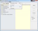
When you select the line “MK AVR Programmer” in the script menu, the script begins to be executed. At the same time, it opens the port, sends a command to the MK to switch to programming mode, receives confirmation from the MK about the successful transition, requests the MK identifier and searches for a description of this MK by its identifier among the available files with descriptions. If it does not find the required description, it displays a corresponding message. If a description is found, then the main menu of the programmer opens. You can see its screenshot in Figure 8. Further understanding is not difficult - the menu is very simple.
In the first version of the script, some functions of a full-fledged programmer are not implemented. For example, there is no way to read and write to EEPROM. But if you open the script in a text editor, you will see that it is very small in size, despite the fact that the main thing is already implemented in it. This suggests that adding the missing functions is not so difficult - the language is very flexible, it allows you to implement rich functionality in a small program. But for most cases, even the existing functions are enough.
Some functionality limitations are described directly in the script text:
//implemented recording only from the zero address (Extended Segment Address Record is ignored, LOAD OFFSET - too)
//the order and continuity of records in the HEX file is not checked
//checksum is not checked
This applies to working with a HEX file, from which the firmware code for the MK is taken. If this file is not corrupted, checking the checksum will have no effect. If it is distorted, it will not be possible to detect it using the script. In most cases, the remaining restrictions will not hurt, but you still need to keep them in mind.
5. Music box - a simple craft for beginners
If you have one of these microcontrollers: ATtiny13, ATtiny44, ATmega8 or ATmega128, you can easily turn it into a music box or music card. To do this, it is enough to write the corresponding firmware into the MK - one of those four that are located in the "MusicBox_..." folders in the same archive with the script. Firmware codes are stored in files with the extension ".hex". Using ATmega128 for such a craft, of course, is “fatty”, just like ATmega8. But this may be useful for testing or experimentation, in other words, for educational purposes. The texts of the programs in Assembler are also attached. The programs were not created from scratch - the music box program from the book by A.V. Belov was taken as a basis. AVR microcontrollers in amateur radio practice." The original program has undergone a number of significant changes:
1. adapted for each of the four MKs: ATtiny13, ATtiny44, ATmega8 and ATmega128
2. buttons have been eliminated - nothing needs to be connected to the controller except power and a sound emitter (melodies are played one after another in an endless loop)
3. the duration of each note is reduced by the duration of the pause between notes to eliminate disturbances in musical rhythm
4. the eighth melody is connected, not used in the book version
5. from the subjective: some “improvements” to optimize and make the algorithm easier to understand
In some melodies one can hear falsehood and even gross errors, especially in “Smile” - in the middle. The ringtone codes were taken from the book (or rather, downloaded from the book’s author’s website along with the original asm file) and have not been modified. Apparently, there are errors in the encoding of the melodies. But this is not a problem - anyone who is “friendly” with music can easily figure it out and fix everything.
In ATtiny13, due to the lack of a 16-bit counter, an 8-bit counter had to be used to reproduce notes, which led to a slight decrease in the accuracy of the notes. But this is hardly noticeable by ear.
About the configuration bits. Their settings must correspond to the state of the new microcontroller. If your MK has been used somewhere before, you need to check the state of its configuration bits, and, if necessary, bring them into line with the settings of the new microcontroller. You can find out the state of the configuration bits of the new microcontroller from the documentation for this MK (section "Fuse Bits"). The exception is ATmega128. This MCU has the M103C bit, which enables compatibility mode with the older ATmega103. Activating the M103C bit greatly reduces the capabilities of the ATmega128, and this bit is active on the new MK. You need to reset the M103C to an inactive state. To manipulate configuration bits, use the corresponding section of the programmer script menu.
There is no point in giving a diagram of the music box: it only contains a microcontroller, power supply and a piezo-sound emitter. Power is supplied in exactly the same way as we did when programming the MK. The sound emitter is connected between the common wire (GND pin of the controller) and one of the MK pins, the number of which can be found in the file with the program assembly code (*.asm). At the beginning of the program text for each MK in the comments there is a line: " sound signal is formed at pin XX." When the programmer script completes its work, the microcontroller exits the programming mode and goes into normal operation mode. Playing melodies begins immediately. By connecting the sound emitter, you can check this. You can leave the sound emitter connected while programming the crystal only if if the audio is coming from a pin not used by the SPI, otherwise the extra capacitance on the pin may interfere with programming.
Task: Let's develop a program to control one LED. When the button is pressed, the LED lights up and when released, it goes out.
First, let's develop a schematic diagram of the device. I/O ports are used to connect any external devices to the microcontroller. Each of the ports is capable of operating as both input and output. Let's connect the LED to one of the ports and the button to the other. For this experiment we will use a controller Atmega8. This chip contains 3 I/O ports, has 2 eight-bit and 1 sixteen-bit timer/counter. Also on board there is a 3-channel PWM, 6-channel 10-bit analog-to-digital converter and much more. In my opinion, a microcontroller is great for learning the basics of programming.
To connect the LED we will use line PB0, and to read information from the button we will use line PD0. The diagram is shown in Fig. 1.
Rice. 1
Through resistor R2, plus supply voltage is supplied to input PD0, which corresponds to a logical one signal. When the button is closed, the voltage drops to zero, which corresponds to a logical zero. In the future, R2 can be excluded from the circuit, replacing it with an internal load resistor, entering the necessary settings in the program. The LED is connected to the output of port PB0 through current-limiting resistor R3. In order to light the LED, you need to apply a logical one signal to the PB0 line. We will use an internal master clock generator at 4 MHz, since the device does not have high requirements for frequency stability.
Now we write the program. I use the programming environment to write programs AVR Studio And WinAvr. Open AVR Studio, a welcome window pops up, click the "Create a new project" button, then select the project type - AVR GCC, write the project name for example "cod1", check both the "Create project folder" and "Create initialization file" checkboxes , click the “Next” button, select “AVR Simulator” in the left window, and “Atmega8” microcontroller type in the right window, click the “Finish” button, the editor and the project category tree opens - the initial settings are completed.
First, let's add standard description text for Atmega8 using the operator for attaching external files: #include
directive syntax #include
#include<имя_файла.h>
#include “filename.h”
Angle brackets< и >indicate to the compiler that included files must first be looked for in the standard WinAvr folder named include. The double quotes “ and “ tell the compiler to start searching in the directory where the project is stored.
Each type of microcontroller has its own header file. For ATMega8 this file is called iom8.h, for ATtiny2313 - iotn2313.h. At the beginning of each program, we must include the header file of the microcontroller we are using. But there is also a common header file io.h. The preprocessor processes this file and, depending on the project settings, includes the required header file in our program.
For us, the first line of the program will look like this:
#include
Any C program must contain one main function. It is named main. Program execution always begins with the execution of the main function. A function has a header - int main(void) and a body - it is limited curly braces {}.
int main(void)
{
function body
}
We will add our code to the body of the function. The return type is indicated before the function name. If the function does not return a value, the key is used void.
int- this is a 2-byte integer number, the range of values is from - 32768 to 32767
After the function name, the parameters that are passed to the function when it is called are indicated in brackets (). If the function has no parameters, the keyword is used void. Function main contains a set of commands, system settings and the main program loop.
Next we configure the port D at the entrance. The port operating mode is determined by the contents of the register DDRD(information transfer direction register). We write the number “0x00” (0b0000000 - in binary form) into this register; nothing is connected to this port except the button, so we configure the entire port D as an input. You can configure the port bit by bit by writing the numbers 0 or 1 into each bit of the register (0-input, 1-output), for example DDRD = 0x81 (0b10000001) - the first and last lines of port D work as output, the rest as input. The internal load resistor must also be connected. The PORTx register controls whether the internal resistors are turned on or off when the port is in input mode. Let's write units there.
Setting up the port B to the exit. The port operating mode is determined by the contents of the register DDRB. Nothing but an LED to the port B not connected, so the entire port can be configured as output. This is done by writing to the register DDRB numbers "0xFF". To prevent the LED from lighting up when you first turn it on, write to the port B logical zeros. This is done by recording PORTB= 0x00;
To assign values, the "=" symbol is used and is called the assignment operator, not to be confused with the "equal" sign.
The port configuration will look like this:
DDRD = 0x00;
PORTD = 0xFF;
DDRB = 0xFF;
PORTB = 0x00;
We write the main loop of the program. while(“while” from English) - this command organizes a loop, repeating the body of the loop many times until the condition is met, that is, while the expression in brackets is true. In C, an expression is considered to be true if it is not equal to zero, and false if it is.
The command looks like this:
while (condition)
{
loop body
}
In our case, the main loop will consist of only one command. This command assigns register PORTB register value to be inverted PORTD.
PORTB = ~PIND; //take the value from port D, invert it and assign it to PORTB (write to PORTB)
// C expressions are read from right to left
PIND information input register. In order to read information from the external output of the controller, you must first switch the desired bit of the port to input mode. That is, write to the corresponding bit of the register DDRx zero. Only after this can a digital signal from an external device be supplied to this pin. Next, the microcontroller will read the byte from the register PINx. The contents of the corresponding bit correspond to the signal on the external pin of the port. Our program is ready and looks like this:
#include
Comments are widely used in the C language. There are two ways to write.
/*A comment*/
//A comment
In this case, the compiler will not pay attention to what is written in the comment.
If you use the same program and connect 8 buttons and 8 LEDs to the microcontroller, as shown in Figure 2, then it will be clear that each bit of the port D matches its port bit B. By pressing the SB1 button, HL1 lights up, by pressing the SB2 button, HL2 lights up, etc.

Figure 2
The article used materials from the book by A.V. Belov. "Tutorial for AVR device developers"
I have said more than once or twice that studying MK should start with assembler. An entire course on the website was devoted to this (although it is not very consistent, but gradually I am combing it to an adequate appearance). Yes, it is difficult, the result will not be on the first day, but you will learn to understand what is happening in your controller. You will know how it works, and not copy other people’s sources like a monkey and try to understand why it suddenly stopped working. In addition, it is much easier for C to create redneck code that will come out with a pitchfork at the most inopportune moment.
Unfortunately, everyone wants results immediately. So I decided to go the other way - make a tutorial on C, but with showing his underwear. A good embedder programmer always holds his piece of hardware tightly by the bolt, not allowing it to take a single step without permission. So first there will be the C code, then what the compiler produced and how it all actually works :)
On the other hand, C's strong point is code portability. If, of course, you write everything correctly. Separating the work algorithms and their hardware implementations into different parts of the project. Then, to transfer the algorithm to another microcontroller, it will be enough to rewrite only the interface layer, where all calls to the hardware are written, and leave all the working code as is. And, of course, readability. The C source code is easier to understand at first glance (although... for example, I don’t care what to point at - be it C or ASM :)), but, again, if everything is written correctly. I will also pay attention to these points.
My debug board will serve as the experimental hardware on which the lion's share of all examples will be installed.
The first C program for AVR
Choosing a compiler and setting up the environment
There are many different C compilers for AVR:
First of all this IAR AVR C- is almost definitely recognized as the best compiler for AVR, because the controller itself was created in close collaboration between Atmel and specialists from IAR. But you have to pay for everything. And this compiler is not only an expensive commercial software, but also has such a ton of settings that it takes a lot of effort to simply compile it in it. I really didn’t develop a friendship with him; the project was rotting due to strange errors at the linking stage (later I found out that it was a crooked crack).
Second comes WinAVR GCC- a powerful optimizing compiler. Fully open source, cross-platform, in general, all the joys of life. It also integrates perfectly into AVR Studio, allowing you to debug right there, which is damn convenient. In general, I chose it.
There is also CodeVision AVR C is a very popular compiler. It became popular due to its simplicity. You can get a working program in it in just a few minutes - the start code wizard greatly facilitates this by stamping out standards for the initialization of all sorts of things. To be honest, I’m kind of suspicious of it - once I had to dismantle a program written by this compiler, it turned out to be some kind of mess and not code. A terrible amount of unnecessary movements and operations, which resulted in a considerable amount of code and slow performance. However, perhaps there was an error in the DNA of the person who wrote the original firmware. Plus he wants money. Not as much as IAR, but noticeable. And in demo mode it allows you to write no more than 2kb of code.
Of course there is a crack, but if you’re going to steal, it’s a million, in the IAR sense :)
There is also Image Craft AVR C And MicroC from microelectronics. I didn't have to use either one, but S.W.G. very praising MicroPascal, they say, a terribly convenient programming environment and libraries. I think MicroC will be no worse, but it’s also paid.
As I said, I chose WinAVR for three reasons: it’s free, it integrates into AVR Studio and there’s just a ton of ready-made code written for it for all occasions.
So download the WinAVR installation with AVR Studio. Next, the studio is installed first, then WinAVR is rolled on top and attached to the studio in the form of a plugin. I strongly recommend installing WinAVR on a short path, something like C:\WinAVR, this way you will avoid a lot of problems with paths.
Creating a project
So, the studio is installed, C is screwed in, it’s time to try to program something. Let's start with the simple, the simplest. Launch the studio, select a new project there, as the AVR GCC compiler and enter the name of the project.
A work field opens with an empty *.c file.
Now it won’t hurt to configure the display of paths in the studio bookmarks. To do this, go to:
Menu Tools - Options - General - FileTabs and select “Filename Only” from the drop-down list. Otherwise, it will be impossible to work - the tab will contain the full path of the file and there will be no more than two or three tabs on the screen.
Project setup
In general, it is considered classic to create a make file in which all dependencies are described. And that's probably right. But for me, who grew up with fully integrated IDEs like uVision or AVR Studio this approach is deeply alien. Therefore, I will do it my way, everything using studio means.
Poke the button with the gear.
 |
These are your project settings, and more precise settings automatic generation of makefile. On the first page you just need to enter the frequency at which your MK will operate. This depends on the fuse bits, so we assume that our frequency is 8000000Hz.
Also pay attention to the optimization line. Now there is -Os - this is size optimization. Leave it as is for now, then you can try to play with this parameter. -O0 is no optimization at all.
The next step is to configure the paths. First of all, add your project directory there - you will add third-party libraries there. The path “.\” will appear in the list.
The Make file has been generated, you can look at it in the default folder in your project, just take a look and see what’s there.
 |
That's all for now. Click OK everywhere and go to the source.
Formulation of the problem
A blank sheet of paper is tempting to implement some cunning idea, since the banal blinking of a diode no longer works. Let's immediately take the bull by the horns and implement the connection with the computer - this is the first thing I do.
It will work like this:
When a one (code 0x31) arrives at the COM port, we will turn on the diode, and when a zero arrives (code 0x30) it turns off. Moreover, everything will be done on interrupts, and the background task will be the blinking of another diode. Simple and meaningful.
Assembling the circuit
We need to connect the USB-USART converter module to the USART pins of the microcontroller. To do this, take a jumper from two wires and place it on the pins crosswise. That is, we connect the Rx of the controller to the Tx of the converter, and the Tx of the converter to the Rx of the controller.
In the end, this is the diagram:
 |
I don’t consider connecting the remaining pins, power, or reset, it’s standard.
Writing code
Let me make a reservation right away that I will not delve specifically into the description of the C language itself. There is simply a colossal amount of material for this, ranging from the classic “C Programming Language” from K&R to various manuals.
I found one such method in my stash; I once used it to study this language. Everything there is short, clear and to the point. I’m gradually putting it together and dragging it onto my website.
It’s true that not all the chapters have been transferred yet, but I think it won’t be for long.
It’s unlikely that I can describe it better, so from the training course, instead of a detailed explanation of the subtleties, I will simply provide direct links to individual pages of this manual.
Adding libraries.
First of all, we add the necessary libraries and headers with definitions. After all, C is a universal language and we need to explain to him that we are working specifically with AVR, so write the line in the source code:
| 1 | #include |
#include
This file is located in the folder WinAVR and it contains a description of all registers and ports of the controller. Moreover, everything there is cunning, with binding to a specific controller, which is transmitted by the compiler via make file in parameter MCU and based on this variable, a header file is connected to your project with a description of the addresses of all ports and registers for this particular controller. Wow! Without it, it’s also possible, but then you won’t be able to use symbolic register names like SREG or UDR and you’ll have to remember the address of each like “0xC1,” which will be a headache.
The team itself #include<имя файла> allows you to add content of any kind to your project text file, for example, a file with a description of functions or a piece of other code. And so that the directive could find this file, we specified the path to our project (the WinAVR directory is already registered there by default).
Main function.
A C program consists entirely of functions. They can be nested and called from each other in any order and different ways. Each function has three required parameters:
- The return value is e.g. sin(x) returns the value of the sine of x. Like in mathematics, in short.
- The transmitted parameters are the same X.
- Function body.
All values transmitted and returned must be of some type, depending on the data.
Any C program must contain a function main as an entry point into the main program, otherwise it’s not C at all :). By the presence of main in someone else’s source code from a million files, you can understand that this is the main part of the program, where everything begins. So let's ask:
| 1 2 3 4 5 | int main(void) ( return 0 ; ) |
int main(void) ( return 0; )
That's it, first simplest program written, it doesn’t matter that it doesn’t do anything, we’ve just started.
Let's figure out what we did.
int This is the data type that the main function returns.
Of course, in a microcontroller main in principle nothing can be returned and in theory there should be void main(void), but GCC was originally designed for PC and there the program can return the value operating system upon completion. Therefore GCC on void main(void) swears by Warning.
This is not an error, it will work, but I don’t like warnings.
void this is the type of data that we pass to the function, in this case main also cannot accept anything from the outside, therefore void- a dummy. A stub is used when there is no need to transmit or return anything.
Here they are { } curly braces are a program block, in this case the body of a function main, the code will be located there.
return- this is the return value that the main function will return upon completion, since we have an int, that is, a number, then we must return a number. Although this still does not make sense, because... on the microcontroller, we can only go nowhere from main. I return null. Because it doesn't matter. But the compiler is usually smart and does not generate code for this case.
Although, if perverted, then from main You can go to the MK - for example, fall into the bootloader section and execute it, but this will require low-level tinkering with the firmware in order to correct the transition addresses. Below you will see for yourself and understand how to do it. For what? This is another question, in 99.999% of cases this is not necessary :)
We did it and moved on. Let's add a variable, we don't really need it and there's no point in introducing variables without it, but we're learning. If variables are added inside the body of a function, then they are local and exist only in this function. When you exit the function, these variables are deleted, and the RAM memory is allocated for more important needs. .
| 1 2 3 4 5 6 | int main(void ) ( unsigned char i; return 0 ; ) |
int main(void) ( unsigned char i; return 0; )
unsigned means unsigned. The fact is that in the binary representation, the most significant bit is allocated to the sign, which means that the number +127/-128 fits into one byte (char), but if the sign is discarded, it will fit from 0 to 255. Usually the sign is not needed. So unsigned.
i is just a variable name. No more.
Now we need to initialize the ports and UART. Of course, you can take and connect the library and call some kind of UartInit(9600); but then you won't know what really happened.
We do this:
| 1 2 3 4 5 6 7 8 9 10 11 12 13 14 15 16 | int main(void ) ( unsigned char i; #define XTAL 8000000L #define baudrate 9600L #define bauddivider (XTAL/(16*baudrate)-1)#define HI(x) ((x)>>8) #define LO(x) ((x)& 0xFF) UBRRL = LO(bauddivider) ; UBRRH = HI(bauddivider) ; UCSRA = 0 ; UCSRB = 1<< RXEN| 1 << TXEN| 1 << RXCIE| 0 << TXCIE; UCSRC = 1 << URSEL| 1 << UCSZ0| 1 << UCSZ1; } |
int main(void) ( unsigned char i; #define XTAL 8000000L #define baudrate 9600L #define bauddivider (XTAL/(16*baudrate)-1) #define HI(x) ((x)>>8) #define LO( x) ((x)& 0xFF) UBRRL = LO(bauddivider); UBRRH = HI(bauddivider); UCSRA = 0; UCSRB = 1< Scary? In fact, there are only five last lines of real code. Everything, that #define It is a preprocessor macro language. Almost the same stuff as in Assembly, but the syntax is slightly different. They will facilitate your routine operations of calculating the necessary coefficients. In the first line we say that instead XTAL you can safely substitute 8000000, and L- indication of the type, saying long is the clock frequency of the processor. The same baudrate— frequency of data transmission via UART. bauddivider already more complicated, instead of it the expression calculated using the formula from the two previous ones will be substituted. So everything that's done is like #define you can safely throw it away, and calculate the necessary numbers on a calculator and immediately enter them into the lines UBBRL = …. and UBBRH = ….. Can. But! Do this ABSOLUTELY IMPOSSIBLE! It will work this way or that way, but you will have so-called magic numbers- values taken from nowhere and for unknown reasons, and if you open such a project in a couple of years, it will be damn difficult to understand what these values are. Even now, if you want to change the speed, or change the quartz frequency, everything will have to be recalculated again, but you changed a couple of numbers in the code and that’s it. In general, if you don’t want to be branded as a coder, then make your code so that it is easy to read, understandable and easy to modify. Then everything is simple: Recording type 1< Done, time to see what happened. Click on compilation and start emulation (Ctrl+F7). Debugging The fact is that initially, in fact, it was on the line UBRRL = LO(bauddivider); After all, what we have in define is not code, but simply preliminary calculations, which is why the simulator is a little dull. But now he realized, the first instruction has been completed and if you climb into the tree I/O View, to the USART section and look at the UBBRL byte there, you will see that the value is already there! 0x33. Take it one step further. See how the contents of the other register change. So go through them all, pay attention to the fact that all the indicated bits are set as I told you, and they are set simultaneously for the entire byte. It won't go any further than Return - the program is over. Opening First there will be tops from the series: 00000000: 940C002A JMP 0x0000002A Jump +00000002: 940C0034 JMP 0x00000034 Jump +00000004: 940C0034 JMP 0x00000034 Jump +00000006: 940C0034 J MP 0x00000034 Jump +00000008: 940C0034 JMP 0x00000034 Jump +0000000A: 940C0034 JMP 0x00000034 Jump +0000000C: 940C0034 JMP 0x00000034 Jump +000000 0E : 940C0034 JMP 0x00000034 Jump +00000010: 940C0034 JMP 0x00000034 Jump +00000012: 940C0034 JMP 0x00000034 Jump +00000014: 940C0034 JMP 0x0000 0034 Jump +00000016: 940C0034 JMP 0x00000034 Jump +00000018: 940C0034 JMP 0x00000034 Jump +0000001A: 940C0034 JMP 0x00000034 Jump +0000001C: 940C0034 JMP 0x00000034 Jump +0000001E: 940C0034 JMP 0x00000034 Jump +00000020: 940C0034 JMP 0x00000034 Jump +00000022: 940C0034 JMP 0x000000 34 Jump +00000024: 940C0034 JMP 0x00000034 Jump +00000026: 940C0034 JMP 0x00000034 Jump +00000028: 940C0034 JMP 0x00000034 Jump This is the interrupt vector table. We will return to it later, but for now just look and remember that it exists. The first column is the address of the flash cell in which the command lies, the second is the command code, the third is the command mnemonic, the same assembly instruction, the third is the operands of the command. Well, automatic comment. 0000002B: BE1F OUT 0x3F,R1 Out to I/O location Recording this zero at address 0x3F. If you look at the I/O view column, you will see that address 0x3F is the address of the SREG register - the flag register of the controller. Those. we reset SREG to run the program on zero conditions. 0000002C: E5CF LDI R28,0x5F Load immediate +0000002D: E0D4 LDI R29,0x04 Load immediate +0000002E: BFDE OUT 0x3E,R29 Out to I/O location +0000002F: BFCD OUT 0x3D,R28 Out to I/O location This is loading the stack pointer. You cannot directly load into I/O registers, only through an intermediate register. Therefore, first LDI to intermediate, and then from there OUT to I/O. I’ll also tell you more about the stack later. For now, know that this is a dynamic memory area that hangs at the end of RAM and stores addresses and intermediate variables. Now we have indicated where our stack will start from. 00000032: 940C0041 JMP 0x00000041 Jump Jump to the very end of the program, and there we have a ban on interrupts and looping tightly on itself: 00000041: 94F8 CLI Global Interrupt Disable +00000042: CFFF RJMP PC-0x0000 Relative jump This is in case of unforeseen circumstances, such as exiting the main function. The controller can be brought out of such a loop either by a hardware reset, or, more likely, by a reset from a watchdog. Well, or, as I said above, correct this in the hex editor and gallop off to wherever our heart desires. Also note that there are two types of transitions: JMP and RJMP; the first is a direct transition to an address. It occupies four bytes and can directly jump through the entire memory area. The second type of transition is RJMP - relative. His command takes two bytes, but he moves from the current position (address) 1024 steps forward or backward. And its parameters indicate the offset from the current point. It is used more often because takes up half the space in a flush, and long transitions are rarely needed. 00000034: 940C0000 JMP 0x00000000 Jump And this is a jump to the very beginning of the code. A reboot of sorts. You can check that all the vectors jump here. The conclusion from this is that if you now enable interrupts (they are disabled by default) and your interrupt occurs but there is no handler, then there will be a software reset - the program will be thrown back to the very beginning. Function main. Everything is similar, you don’t even need to describe it. Just look at the already calculated number being entered into the registers. The compiler preprocessor rocks!!! So no “magic” numbers! 00000036: E383 LDI R24,0x33 Load immediate +00000037: B989 OUT 0x09,R24 Out to I/O location 15: UBRRH = HI(bauddivider); +00000038: BC10 OUT 0x20,R1 Out to I/O location 16: UCSRA = 0; +00000039: B81B OUT 0x0B,R1 Out to I/O location 17: UCSRB = 1< And here's the bug: 0000003E: E080 LDI R24.0x00 Load immediate +0000003F: E090 LDI R25.0x00 Load immediate +00000040: 9508 RET Subroutine return The question is, why does the compiler add such tops? And this is nothing more than Return 0, we defined the function as int main(void) and so we wasted another four bytes for nothing :) And if you make void main(void) then only RET will remain, but a warning will appear, that our main function does not return anything. In general, do as you please :) Difficult? Apparently not. Click step-by-step execution in disassembler mode and see how the processor executes individual instructions, what happens to the registers. How does movement through commands and final looping occur? To be continued in a couple of days... Offtop: If you are reading this article, you probably have a desire to understand how microcontrollers work, and most likely have questions: Let's try to answer these questions. In industry, somewhat differently, the first place by a large margin is occupied by Renesas Electronics on the second Freescale, on the third Samsung, then go Microchip And T.I., then all the rest. We will study 8-bit AVR microcontrollers, families ATMEGA 8 and 16 series. The choice was determined, again, by accessibility, the presence of many amateur developments, and a huge amount of educational material. The presence of a variety of built-in components and functionality of this family. The most common ones AVRStudio, ATmelStudio, WINAVR, CodeVision, IAR Embedded Workbench. ATmelStudio allows you to create projects and write programs both in assembler and in SI. Initially, the question is always: what programming language should I choose in order to write effective programs? My answer is simple: you need to be able to write in at least two languages: assembly and SI. Assembly language is simply necessary when you need to write fast and compact subroutines and macros, and various device drivers. But, when you need to create a large project built on complex algorithms, without knowledge of SI, a lot of time can be spent, especially in the debugging process, and if there is a desire to transfer it to another platform, for example PIC18, or STM, it can become an insoluble problem. To clearly see the result of your work without using a soldering iron or breadboard, just install the program Proteus. Non-volatile program and data memory Embedded Peripherals Special microcontroller functions I/O pins and housings Operating voltages Operating frequency differences between ATMEGA16 and 8 JTAG interface (IEEE 1149.1 compliant) Four channels PWM/PWM 8-channel 10-bit analog-to-digital converter Six low consumption modes: Idle, Power-save, Power-down, Standby, Extended Standby and ADC noise reduction 32 programmable I/O lines 40-pin PDIP package and 44-pin TQFP package To create a project, you need to open the program, the following screensaver will appear, and the project creation page will open To create a new project, you need to click on "New Project..." The following window will appear Choose “megaAVR, 8-bit” and find the microcontroller we need, we chose ATmega8. On the right side of the screen saver, a list of devices that work with this microcontroller appears, one of which we can connect. Choose OK. The text editor page appears, which allows you to edit and debug the program. While the page is blank, the time and date of creation and the name of the project file, user name are indicated. There are additional I/O devices window and program compilation reports window. now we Hello, MySku residents! The hero of our review is the Atmega8A-16PU microcontroller. I will tell you about programming this microcontroller in the CodeVisionAvr integrated development environment, we will blink the LED, and we will consider the pros and cons of working in this environment. Perhaps in the future this will serve as an alternative for you to the already “popular” Arduino. If you are interested, go to cut. Specifications: Additional Information How to register these same fuses?! For this I used the AvrDude program, it is free and can be easily found on the Internet. In order to correctly set the fuses in accordance with the desired frequency, look at the datasheet, or you can use a simple one. Let's get a footcloth like this /******************************************************* Void main(void) // Input/Output Ports initialization // Port C initialization // Port D initialization // Timer/Counter 0 initialization // Timer/Counter 1 initialization // Timer/Counter 2 initialization // Timer(s)/Counter(s) Interrupt(s) initialization // External Interrupt(s) initialization //USART initialization // Analog Comparator initialization //ADC initialization // SPI initialization // TWI initialization While (1) Additional Information
Well and L.O. And HI the low and high bytes will be taken from this result, because It obviously may not fit into one byte. IN HI X (the macro input parameter) is shifted eight times to the right, resulting in only the most significant byte remaining. And in L.O. we do a bitwise AND with the number 00FF, as a result only the low byte will remain.
All these “UBRRL and Co” are configuration registers of the UART transmitter with the help of which we will communicate with the world. And now we have assigned them the required values, setting them to the desired speed and mode.
All sorts of progress bars ran through, the studio changed and a yellow arrow appeared near the entrance to the main function. This is where the processor is currently running and the simulation is paused.
Now reset the simulation to zero. Click there Reset (Shift+F5). Open the disassembled listing, now you will see what is actually happening in the controller. View -> Disassembler. And not YYAAAAAA!!! Assembler!!! HORROR!!! AND IT IS NECESSARY. So that later, when something goes wrong, you don’t be stupid in the code and don’t ask lame questions on the forums, but immediately get into the guts and see where you’re stuck. There's nothing scary there. 1
2
3
4
5
6
7
8
9
10
11
12
13
14
15
16
17
18
19
20
21
+00000000: 940C002A JMP 0x0000002A Jump +00000002: 940C0034 JMP 0x00000034 Jump +00000004: 940C0034 JMP 0x00000034 Jump +00000006: 940C0034 J MP 0x00000034 Jump +00000008: 940C0034 JMP 0x00000034 Jump +0000000A: 940C0034 JMP 0x00000034 Jump +0000000C: 940C0034 JMP 0x00000034 Jump + 0000000E: 940C0034 JMP 0x00000034 Jump +00000010: 940C0034 JMP 0x00000034 Jump +00000012: 940C0034 JMP 0x00000034 Jump +00000014: 940C0034 J MP 0x00000034 Jump +00000016: 940C0034 JMP 0x00000034 Jump +00000018: 940C0034 JMP 0x00000034 Jump +0000001A: 940C0034 JMP 0x00000034 Jump +000000 1C : 940C0034 JMP 0x00000034 Jump +0000001E: 940C0034 JMP 0x00000034 Jump +00000020: 940C0034 JMP 0x00000034 Jump +00000022: 940C0034 JMP 0x0000 0034 Jump +00000024: 940C0034 JMP 0x00000034 Jump +00000026: 940C0034 JMP 0x00000034 Jump +00000028: 940C0034 JMP 0x00000034 Jump
So, if you look, there are continuous transitions. And the JMP command code is four bytes, it contains the jump address written backwards - the low byte at the low address and the jump command code 940C 1
2
3
4
+0000002C: E5CF LDI R28,0x5F Load immediate +0000002D: E0D4 LDI R29,0x04 Load immediate +0000002E: BFDE OUT 0x3E,R29 Out to I/O location +0000002F: BFCD OUT 0x3D,R28 Out to I/O location
1
2
+00000041: 94F8 CLI Global Interrupt Disable +00000042: CFFF RJMP PC-0x0000 Relative jump
1
+00000034: 940C0000 JMP 0x00000000 Jump
1
2
3
4
5
6
7
8
9
10
11
12
< 1
2
3
+0000003E: E080 LDI R24.0x00 Load immediate +0000003F: E090 LDI R25.0x00 Load immediate +00000040: 9508 RET Subroutine return
Alexei78 I created a plugin for Firefox that makes it easier to navigate my site and forum.
Discussion and downloading,
Modern amateur radio cannot be imagined without microcontrollers, and this is obvious. In recent decades, microcontrollers from various manufacturers have become widespread in various fields of human activity. They can often be found in the most unexpected devices and designs. You and I are witnessing the computerization and automation of the processes around us. The truth is that without knowledge of the basics of programming, it has become almost impossible to create modern competitive devices...
4. What literature should I study?
1. Which microcontroller should I choose for the job?
8-bit microcontrollers are very popular among radio amateurs. PIC Microchip Technology and AVR Atmel, 16-bit MSP430 from TI, as well as 32-bit microcontrollers, architectures ARM.
Popularity is determined by price and availability; the availability of technical information and the cost of software support play a significant role.2. Which development environment should I use to program the selected microcontroller?
Various integrated development environments (IDE, Integrated development environment) have been created for AVR.
IDE is a software system used by programmers to develop software, which includes:
text editor,
compiler and/or interpreter,
assembly automation tools,
debugger
In order to write programs, we will use the free IDE ATmelStudio version 6 and higher.
You can download Atmel Studio from the official website after registration (registration is absolutely free and does not oblige you to anything!)
In addition, hardware computing platforms have now appeared Arduino, work with which requires knowledge of the SI++ language.
Therefore, we will write programs both in assembler and in SI.3. How to flash the controller, and what additional devices and accessories are needed for convenient work with them?
We use Datagorian. In addition, you will need to purchase breadboards and a power supply with an output voltage of 5 Volts. You can use it as a low-ripple power supply by using a 5-volt zener diode.
Perhaps, over time, Igor and I will propose a project for assembling a debug board. 


4. What literature should I study?
But, for example:
Practical programming of AVR in assembler. Revich, 2011
1000 and one microcontroller circuit Vol. 1-2. Ryumik, 2010-2011
10 practical devices on the AVR MK Book 1-2. Kravchenko, 2008-2009
A tutorial for a device developer using the AVR MK. Belov, 2008
MK AVR families Tiny and Atmega. Efstifeev, 2008
CodeVisionAVR. A guide for beginners. Lebedev, 2008
Microprocessor control of devices, thyristors, relays. Belov, 2008
Analog interfaces MK. Steward, Ball, 2007
We create devices on the AVR MK. Belov, 2007
MK AVR in amateur radio practice. Full analysis of ATTINY2313. Belov, 2007
Network and internetwork data exchange with MK. Go, 2007
MK AVR. workshop for beginners. Hartov, 2007
Application of AVR Schemes, algorithms, programs. Baranov, 2006
AVR microcontrollers. Introductory course. Morton, 2006
Measurement, control and regulation using AVR. Trumpert, 2006
Programming in C language for AVR and PIC MK. Shpak, 2006
Design of devices on MK. Belov, 2005
MK - it's simple, volumes 1-3. Frunze, 2002-2003
The C Programming Language, 2nd edition. Kernighan, Ritchie, 2009
Programming ATMEL microcontrollers in the language S. Prokopenko, 2012 5. Where on the Internet can you ask questions and get specific answers?
You can ask questions on our or any other forum where topics on microcontrollers are touched upon in one way or another. The main thing on forums is to formulate questions correctly in order to clearly receive answers. Abstract questions are not welcome, and most likely you will receive harsh criticism instead of an answer, or your question will remain unanswered! Now let's take a closer look at our favorite, the ATMEGA 8 microcontroller
8-bit, high-performance, low-power AVR microcontroller
Progressive RISC architecture
130 high-performance instructions, most instructions executed in one clock cycle
32 8-bit general purpose working registers
Completely static operation
Performance approaching 16 MIPS (at 16 MHz clock speed)
Built-in 2-cycle multiplier
8 KB of In-System Self-Programmable Flash memory
Provides 1000 erase/write cycles
Additional boot code sector with independent lock bits
Provides simultaneous read/write mode (Read-While-Write)
512 bytes EEPROM
Provides 100,000 erase/write cycles
1 KB on-chip SRAM
Programmable locking to protect user software
Two 8-bit timer/counters with separate prescaler, one with compare mode
One 16-bit timer/counter with separate prescaler and capture and compare modes
Real time counter with separate generator
Three PWM channels
8-channel A/D converter (TQFP and MLF)
6 channels with 10-bit precision
6-channel analog-to-digital converter (in PDIP package)
4 channels with 10-bit precision
2 channels with 8-bit precision
Byte-oriented 2-wire serial interface
Programmable Serial USART
Serial interface SPI (master/slave)
Programmable watchdog timer with separate built-in oscillator
Built-in analog comparator
Power-on reset and programmable brownout detection
Built-in calibrated RC oscillator
Internal and external interrupt sources
Five low consumption modes: Idle, Power-save, Power-down, Standby and ADC noise reduction
23 programmable I/O lines
28-pin PDIP package, 32-pin TQFP package, and 32-pin MLF package
2.7 - 5.5 V (ATmega8L)
4.5 - 5.5 V (ATmega8)
0 - 8 MHz (ATmega8L)
0 - 16 MHz (ATmega8)
16 KB of In-System Self-Programmable Flash memory
Peripheral scanning capability compliant with JTAG standard
Expanded support for embedded debugging
Programming via JTAG interface: Flash, EEPROM memory, jumpers and lock bits
8 unbalanced channels
7 differential channels (TQFP package only)
2 differential channels with programmable gain of 1x, 10x or 200x (TQFP package only)

AtmelStudio
If you are just starting out, then you need to download and install the AtmelStudio program from the official page atmel.com
After installing the AtmelStudio program, you can start creating a project.
Project- this is your program that you will write, debug and flash, after compilation, into the memory of the microcontroller. 

In this case, a new window will open where you can select the programming language, the name of the project, its location, the name of the package with the project files and the ability to create a directory for further use in other cross-projects. To create a project where we will program in assembler, we need to select - Assembler, after that we change the name of the project, its location, and select OK.


We can program in assembler.
A project for programming in SI language is created in the same way.
Preamble.
It just so happened that I started my acquaintance with MK with Arduino. I blinked the LED, connected various sensors and shields, and made various projects. Everything worked, I was satisfied, but I wanted something more. I came across one project where Atmega8A is involved, for which I need to write the firmware myself. It was he who pushed me to study the process of programming a “naked” MK.
So, we have a microcontroller from Atmel, AVR Atmega8A family. 
Pinout: 
Here is
Now for operation and programming you need to connect it to the programmer according to the diagram: 
Unfortunately, I’m like a shoemaker - without boots, now I don’t have a programmer at hand, so I’ll use Arduino UNO to load the finished firmware into the microcontroller and configure the fuses. You just need to download the “Arduinoisp” sketch from the Arduino IDE examples folder and connect it according to the diagram: 
However, this solution has a significant drawback, which I will talk about a little later. Before we start writing a program in CodeVisionAvr (hereinafter referred to as CvAvr), we need to decide at what frequency our microcontroller will operate. By default, from the factory, our hero operates from an internal rc generator at a frequency of 1 MHz (with the ability to reconfigure to 2, 4, and 8 MHz). Since the internal rc generator is calibrated at the factory under certain conditions (exact voltage, temperature), the accuracy of its operation in “field” conditions may differ from 3% to 10%. For tasks where high timing accuracy is not needed, this can be neglected; in other cases, it is better to use external quartz. In my project I used an external quartz at a frequency of 8 MHz. Now we need to “explain” to the MC that it needs to work from external quartz. This is done by changing the fuses. To put it in simple terms, this is something like a BIOS, like on a motherboard, where you indicate its operating modes; similarly, we tell the MK in which modes, in addition to the frequency, it should operate. All information will be stored in non-volatile memory.
I’ll tell you about fusing firmware under the spoiler; those who know how to do it themselves can scroll further.
We set the parameters as in the picture. 
Everything is simple here:
Clock Source - set the frequency (External Crystal 3 - 16 Mhz) from the external quartz.
Start-up Time - MC start speed after RESET is removed or power is applied (16K CK + 4.1ms fast).
Check the box: Ext. Clock/RC Osc./Low-freq. Crystal: enable internal Capacitors (36 pF)
Internal R/C Osc.: leave unchecked! External Crystal: enable full swing (necessary for >8 MHz).
Thus, we got Low Fuse 0xEF and High Fuse 0xC9. Great, half the job done. Now we connect the microcontroller to the Arduino UNO, and the Arduino itself to the computer, respectively. Launch the command line, go to the folder with AvrDude. Next, enter the line: avrdude -C avrdude.conf -c avrisp -P COM13 -b 19200 -p m8 -U lfuse:w:0xef:m -U hfuse:w:0xc9:m
This is what it looks like in the picture: 
Let's parse the line you entered:
avrisp is a type of our Arduino-like programmer
COM13 is the com port number that identifies our Arduino in the system (in your case you need to look it up in the device manager)
19200 - com port speed, leave as is
m8 - indicate that our MK is Atmega8
-U lfuse:w:0xef:m -U hfuse:w:0xc9:m - our Low Fuse 0xEF and High Fuse 0xC9 are indicated here
Be PLEASE CAREFUL!!, Incorrectly specified Fuse can lead to the MK becoming bricked (we don’t need dancing with a tambourine to restore it).
We press “Enter” and at the output we get the result, as in the picture: 
If no errors appear during the process, then the work is done, our microcontroller will now work from external quartz.
You can read about fuses in great detail and also by searching on Google.
Now we are ready to start programming. For myself, I chose the CvAvr development environment. The programming language will be different from Arduino; in CvAvr it is C-like. Let's write our first Blink.
After installing and launching the environment, we will use the Project Creation Wizard. Select “File” - “New” - “Project”. When asked whether we will use the wizard, we answer in the affirmative. Target AVR Chip Type: AT90, ATtity, ATmega.
This is what the Project Wizard looks like: 
On the Chip tab, select ATmega8A, Clock 8.000000 Mhz. Go to the Ports tab. Our LED will be connected to pin 14 of the microcontroller, according to the pinout - PB0. On the tab, select Port B, Bit 0 switch from IN to OUT, i.e. We switch the operating mode of the 14th leg of our microcontroller to the output. 
This completes the master's work. Select “Program” - “Generate, Save and Exit”. We save our project, for example, under the name Blink.
This program was created by the
CodeWizardAVR V3.12 Advanced
Automatic Program Generator
Chip type: ATmega8A
Program type: Application
AVR Core Clock frequency: 8.000000 MHz
Memory model: Small
External RAM size: 0
Data Stack size: 256
*******************************************************/
#include
#include
// Declare your global variables here
{
// Declare your local variables here
// Port B initialization
// Function: Bit7=In Bit6=In Bit5=In Bit4=In Bit3=In Bit2=In Bit1=In Bit0=Out
DDRB=(0<
PORTB=(0<
// Function: Bit6=In Bit5=In Bit4=In Bit3=In Bit2=In Bit1=In Bit0=In
DDRC=(0<
PORTC=(0<
// Function: Bit7=In Bit6=In Bit5=In Bit4=In Bit3=In Bit2=In Bit1=In Bit0=In
DDRD=(0<
PORTD=(0<
// Clock value: Timer 0 Stopped
TCCR0=(0<
// Clock source: System Clock
// Clock value: Timer1 Stopped
// Mode: Normal top=0xFFFF
// OC1A output: Disconnected
// OC1B output: Disconnected
// Noise Canceller: Off
// Input Capture on Falling Edge
// Timer1 Overflow Interrupt: Off
// Input Capture Interrupt: Off
// Compare A Match Interrupt: Off
// Compare B Match Interrupt: Off
TCCR1A=(0<
TCNT1L=0x00;
ICR1H=0x00;
ICR1L=0x00;
OCR1AH=0x00;
OCR1AL=0x00;
OCR1BH=0x00;
OCR1BL=0x00;
// Clock source: System Clock
// Clock value: Timer2 Stopped
// Mode: Normal top=0xFF
// OC2 output: Disconnected
ASSR=0<
OCR2=0x00;
TIMSK=(0<
// INT0: Off
// INT1: Off
MCUCR=(0<
// USART disabled
UCSRB=(0<
// Analog Comparator: Off
// The Analog Comparator's positive input is
// connected to the AIN0 pin
// The Analog Comparator's negative input is
// connected to the AIN1 pin
ACSR=(1<
//ADC disabled
ADCSRA=(0<
// SPI disabled
SPCR=(0<
// TWI disabled
TWCR=(0<
{
There is nothing to worry about here; the project specifies the operating modes of ports, timers, interrupts, USART, Analog Comparator, ADC, SPI and connected libraries. In short, all the parameters that we specified in the wizard, everything except the ports and the chip, are configured by default. We will write the main program loop in while (1) (program text). Because we are working with PB0 (14 leg), in the program loop we will write:
while (1)
{
PORTB.0=1;
delay_ms(1000);
PORTB.0=0;
delay_ms(1000);
}
Here we set PB0 high, wait 1 second and set low, then the cycle repeats. Don’t forget to include the library at the beginning of the project #include 
The size of our program was 198 bytes, and took up 2.4% of the micron's memory.
Next we assemble the diagram: 
Now go to the folder with our project, go to the “Debug” folder, then “Exe”, there is a file with a hex extension. In my case it's blink.hex.
There's one last step left. Copy this file to the folder with AvrDude. We launch the command line again, go to our folder. Enter the line avrdude -C avrdude.conf -c avrisp -P COM13 -b 19200 -p m8 -U flash:w:blink.hex
This is what it looks like in the picture: 
If everything is entered correctly, press “Enter” 
Congratulations! The job is done, the LED should blink happily for you :)
Conclusion.
In conclusion, I want to say about the disadvantage of the Arduino-like programmer; CvAvr simply does not support it. Having, for example, AVRISP mkII in hand, you can flash the fuses and download the program directly from CodeVisionAvr. By the way, the homebrew programmer also refused to use the AvrDude graphical interface and worked only from the command line.
I figured out CodeVisionAvr pretty quickly; the Internet is full of text and video lessons. In a couple of weeks I mastered the operation of hardware PWM, interrupts, timers, working with buttons and connecting a graphic display. Specifically, I had to do part of my project: organize a hardware 16-bit PWM on the Atmega8, connect 2 buttons to control it, and also display its operating modes on a graphic display, which I did with ease :) Here are a couple of photos: 

Results in comparison with Arduino:
+ Understanding CvArv is not difficult because there is a project creation wizard;
+ Availability of plug-in libraries, there are enough of them;
+ Fast compilation;
+ The ability to simulate a project in Proteus, as well as debug it using the built-in debugger;
+ The size of the program is several times smaller. Standard Blink took us 198 Bytes, a similar sketch in Arduino IDE 1084 Bytes + 2 KB bootloader;
+ Ability to implement modes that cannot be done on Arduino. For example, 16-bit PWM (in general, it’s possible on Arduino, but only with “crutches”);
+ The ability to use ATtiny, ATmega microcontrollers for your projects where Arduino would be redundant;
- Still, it’s better for a beginner to start mastering MK with Arduino;
- The programming language is different from Arduino processing;
- There are still more libraries for Arduino;
- CodeVisionAvr is a paid program, there are free versions with limitations;
By programming the “naked” microcontroller in CodeVisionAvr, I gained a lot of experience. Studying timers, registers, operating modes, architecture, reading datasheets will increase your skills, broaden your horizons and open up new aspects of working with microcontrollers.
As a bonus, I'm attaching a couple of photos when I figured out the graphic LCD display and played around a little. 

P.s. There’s a lot more I wanted to write about, but this won’t be a review, but a huge article. I am ready to answer questions within my competence, in private or in comments. You can watch a lot of lessons on AVR.