DIY subwoofer: from entry-level to high-end. Do-it-yourself active home subwoofer Chips for standard subwoofers in cars
- About computer calculations
- What is this and why?
- What kind of speaker do you need?
- System structure
- Decor
- Car subwoofers
- It couldn't be simpler
- It's also simple
- Powerful 6th order
- 4th order
- Electronics
- How to calculate a subwoofer?
In this article we will look at how to make a subwoofer with your own hands, without delving into the depths of electroacoustics, without resorting to complex calculations and subtle measurements, although you will still have to do some things. “Without any special difficulties” does not mean “slap on a brick, drive away, grandma, mogarych.” These days on home computer you can simulate very complex acoustic systems (AS); See the end for a link to a description of this process. But working with a finished device on a whim gives something that you cannot get by any reading or viewing - an intuitive understanding of the essence of the process. In science and technology, discoveries at the tip of a pen are rarely made; Most often, a researcher, having gained experience, begins to “gut” understand what’s what, and only then looks for mathematics suitable for describing the phenomenon and deriving design engineering formulas. Many great people recalled their first unsuccessful experiences with humor and pleasure. Alexander Bell, for example, initially tried to wind the coils for his first telephone with bare wire: he, a musician by training, simply did not yet know that live wire needed to be insulated. But Bell still invented the telephone.
About computer calculations
Do not think that JBL SpeakerShop or other acoustics calculation program will give you the only possible, most correct option. Computer programs are written using established, proven algorithms, but non-trivial solutions are impossible only in theology. “Everyone knows that you can’t do this. There is a fool who doesn't know this. He is the one who makes the invention."– Thomas Alva Edison.
SpeakerShop appeared not so long ago, this application was developed very thoroughly and the fact that it is used very actively is an absolute plus for both developers and amateurs. But in some ways the current situation with him is similar to the story with the first photoshops. Who else used Windows 3.11, remember? - back then they just went crazy with image processing. And then it turned out that in order to take a good picture, you still need to know how to take photographs.
What is this and why?
A subwoofer (simply a sub) in its literal translation sounds funny: a burr. In reality, this is a bass (low-frequency, woofer) speaker that reproduces frequencies below approx. 150 Hz, in a special acoustic design, a box (box) of a rather complex device. Subwoofers are also used in everyday life, in high-quality floor-standing speakers and inexpensive desktop ones, built-in and in cars, see fig. If you manage to make a subwoofer that reproduces bass correctly, you can safely take on any speaker, because LF reproduction is perhaps the fattest of the whales on which all electroacoustics stand.
It is much more difficult to make a compact low-frequency section of the speaker system than the mid-range and high-frequency (mid- and high-frequency) parts, firstly, due to an acoustic short circuit, when sound waves from the front and rear radiating surfaces of the speaker (loudspeaker head, GG) cancel each other out: lengths LF waves are meters, and without proper acoustic design of the GG, nothing prevents them from immediately converging in antiphase. Secondly, the spectrum of sound distortion in the low frequencies extends far into the best audible region of the midrange. In essence, any broadband speaker has a low-frequency section into which midrange and high-frequency emitters are built. But from the point of view of ergonomics, an additional requirement is imposed on the subwoofer: a subwoofer for the home should be as compact as possible.
Note: All types of acoustic design of LF GG can be divided into 2 large classes - some dampen the radiation from the rear of the speaker, the second reverse it in phase by 180 degrees (turn the phase) and re-radiate it from the front. A subwoofer, depending on the properties of the GG (see below) and the required type of its amplitude-frequency response (AFC), can be built according to a circuit of one class or another.
People can distinguish the direction of sounds below 150 Hz very poorly, so in an ordinary living room a sub can be placed basically anywhere. MF-HF speakers (satellites) of acoustics with a subwoofer are very compact; their location in the room can be selected optimally for the given room. Modern housing is, to put it mildly, no different in terms of excess space and good acoustics, and it is not always possible to “stuff” at least a couple of good broadband speakers into it correctly. Therefore, making a subwoofer yourself allows you not only to save a very significant amount of money, but also to still get a clear, true sound in this Khrushchev, Brezhnevka or modern new building. A subwoofer is especially effective in full surround sound systems, because... putting 5-7 columns on a full page each is too much even for the most sophisticated users.
Bass
Reproducing bass is not only technically difficult. The generally narrow low-frequency region of the entire spectrum of sound waves is heterogeneous in its psychophysiological effect and is divided into 3 regions. To choose the right bass speaker and make a subwoofer box with your own hands, you need to know their boundaries and meaning:
- Upper bass (UpperBass) – 80-(150…200) Hz.
- Average bass or midbass (MidBass) – 40-80 Hz.
- Deep bass or sub-bass (SubBass) – below 40 Hz.
Top
Middle
For midbass, the main task when creating a subwoofer is to ensure the highest GG output, a given shape of the frequency response and its maximum uniformity (smoothness) in the minimum volume of the box. The frequency response, which is close to rectangular towards lower frequencies, gives a powerful but harsh bass; Frequency response, uniformly falling - clean and transparent, but weaker. The choice of one or the other depends on the nature of what you are listening to: rockers need an “angrier” sound, while classical music needs a gentler sound. In both cases, large dips and spikes in the frequency response spoil the subjective perception with formally identical sound technical parameters.
Depth
FI
Note: a passive radiator (PI) is equivalent in all respects - instead of a pipe with a port, a bass speaker is installed without a magnetic system and with a weight instead of a coil. There are no “tuning-free” methods for calculating PI, which is why PI is a rare exception in industrial production. If you have a burnt-out bass speaker lying around, you can experiment - the adjustment is made by changing the weight of the load. But keep in mind that it is better not to make an active PI for the same reason as a closed box.
About deep crevices
Acoustics with deep slots (items 4, 6, 8-10) are sometimes identified with FI, sometimes with a labyrinth, but in fact this is an independent type of acoustic design. There are many advantages to a deep slit:
The deep slot has only one drawback, and only for beginners: it is not adjustable after assembly. As it is done, so it will sing.
About anti-acoustics

Bandpasses
BandPass means band pass, which is the name given to speakers without direct radiation of sound into space. This means that bandpass speakers do not emit midrange due to its internal acoustic filtering: the speaker is placed in a partition between resonating cavities that communicate with the atmosphere through pipe ports or deep slots. Bandpass is an acoustic design specific to subwoofers and is not used for completely separate speakers.
Bandpasses are divided by order of magnitude, and the order of a bandpass is equal to the number of its own resonant frequencies. High-quality GGs are placed in 4th-order bandpasses, where it is easy to organize acoustic damping (position 5); low- and medium-quality - in 6th order bandpasses. Contrary to popular belief, there is no noticeable difference in sound quality between the two: already at the 4th order the frequency response at low frequencies is smoothed to 2 dB or less. The difference between them for an amateur is mainly in the difficulty of setting: in order to accurately adjust the 4th bandpass (see below), you will have to move the partition. As for 8th order bandpasses, they obtain 2 more resonant frequencies due to the acoustic interaction of the same 2 resonators. Therefore, 8th bandpasses are sometimes called 6th order class B bandpasses.
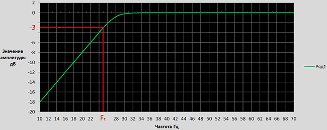
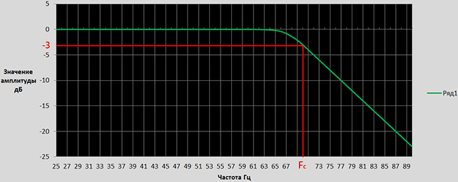
Note: idealized frequency response at low frequencies for some types of acoustic design are shown in Fig. red. The green dotted line shows the ideal frequency response from the point of view of the psychophysiology of hearing. It can be seen that there is still enough work in electroacoustics.

Amplitude-frequency characteristics of the same loudspeaker head in different acoustic designs
Car subwoofers
Car subwoofers are usually placed either in the cargo compartment, or under the driver’s seat, or behind the back of the rear seat, pos. 1-3 in Fig. In the first case, the box takes up useful volume, in the second, the sub works in difficult conditions and can be damaged by feet, in the third, not every passenger will be able to tolerate powerful bass right next to their ears.

Recently, car subwoofers are increasingly being made of the stealth type, built into the rear fender niche, pos. 4 and 5. Sufficient sub-bass power is achieved by using special auto speakers with a diameter of 12” with a rigid diffuser, which is little susceptible to the membrane effect, pos. 5. How to make a subwoofer for a car by molding a wing niche, see next. video.
Video: DIY stealth car subwoofer
It couldn't be simpler
A very simple subwoofer that does not require a separate bass amplifier can be made using a circuit with independent sound emitters (IS), see fig. In fact, these are two channel LF GGs placed in a common long housing installed horizontally. If the length of the box is comparable to the distance between the satellites or the width of the TV screen, the “blurring” of the stereo is hardly noticeable. If listening is accompanied by viewing, it is completely unnoticeable due to involuntary visual correction of the localization of sound sources.

Using the scheme with independent FMs, you can make an excellent subwoofer for a computer: a box with speakers is placed in the far upper corner under the tabletop. The cavity underneath is a resonator tuned to a very low frequency, and an unexpectedly good sub-bass comes out from the small box.
FI for a subwoofer with independent FIs can be calculated in the speaker shop. In this case, the equivalent volume Vts is taken twice as large as measured, the resonant frequency Fs is 1.4 times lower, and the total quality factor Qts is 1.4 times higher. The material of the box, as elsewhere below, is MDF from 18 mm; for subwoofer power from 50 W – from 24 mm. But it is better to place the speakers in a closed box; in this case, it can be done without calculation: the length inside is taken at the installation site, ranging from 0.5 m (for a computer) to 1.5 m (for a large TV). The internal cross-section of the box is determined based on the diameter of the speaker cone:
- 6” (155 mm) – 200x200 mm.
- 8” (205 mm) – 250x250 mm.
- 10” (255 mm) – 300x300 mm.
- 12” (305 mm) – 350x350 mm.
In the worst case (an under-table computer sub with 6” speakers), the volume of the box will be 20 liters, and the equivalent with filling will be 33-34 liters. With a UMZCH power of up to 25-30 W per channel, this is enough to get decent midbass.
Filters
In this case, it is better to use LC filters of type K. They require more coils, but in amateur conditions this is not essential. K-filters have low attenuation in the stopband, 6 dB/oct per link or 3 dB/oct per half-link, but have an absolutely linear phase response. In addition, when operating from a voltage source (which, with great accuracy, is the UMZCH), the K-filter is little sensitive to changes in load impedance.
At pos. 1 pic. Diagrams of K-filter sections and calculation formulas for them are given. R for the low-frequency GG is taken equal to its impedance Z at the low-pass filter cutoff frequency of 150 Hz, and for the high-pass filter equal to the satellite impedance z at the high-pass filter cutoff frequency of 185 Hz (formula in position 6). Z and z are determined according to the diagram and formula in Fig. above (with measurement diagrams). Working diagrams of filters are given in pos. 2. If you prefer to buy additional capacitors rather than wind coils, exactly the same parameters can be made from P-links and half-links.

Data and circuits for making filters for a simple subwoofer with independent emitters
The attenuation of the low-pass filter in the stopband is 18 dB/oct, and the attenuation of the high-pass filter is 24 dB/oct. This frankly non-trivial ratio is justified by the fact that the satellites are unloaded from the low frequencies and give a cleaner sound, and the remainder of the low frequencies reflected from the high-pass filter is sent to the low-frequency speakers and makes the bass deeper.
Data for calculating filter coils are given at pos. 3. They need to be positioned mutually perpendicular because K-filters operate without magnetic coupling between the coils. When calculating, the dimensions of the coil are specified and the number of turns is determined using the inductance found in the order of calculating the filter. Then, using the laying coefficient, the diameter of the wire in the insulation is found; it should be at least 0.7 mm. It turns out less - increase the size of the coil and recalculate.
Settings
Setting up this subwoofer comes down to equalizing the volumes of the bass and satellite speakers, respectively. cutoff frequencies. To do this, first prepare the room for acoustic measurements, as described above, and a tester with a bridge and transformer. Next you will need a condenser microphone. For a computer one, you will have to make some kind of microphone amplifier (MCA) with bias applied to the capsule, because a regular sound card cannot simultaneously receive a signal and emulate a frequency generator, pos. 4. If you can find a condenser microphone with a built-in MUS, even an old MKE-101, great, its output is connected directly to the primary (smaller) winding of the transformer. The measurement procedure is simple:
- The microphone is fixed opposite the geometric center of the satellites at a horizontal distance of 1-1.5 m.
- Disconnect the subwoofer from the UMZCH and apply a 185 Hz signal.
- Record the voltmeter readings.
- Without changing anything in the room, they turn off the satellites and connect the sub.
- A 150 Hz signal is supplied to the UMZCH and the tester readings are recorded.
Now you need to calculate the equalizing resistors. The volumes are equalized by muting the louder links in a series-parallel circuit (item 5), because it is necessary to keep the previously found values of Z and z unchanged modulo. Calculation formulas for resistors are given in pos. 6. Power Rg – not less than 0.03 of the power of the UMZCH; Rd – any from 0.5 W.
It's also simple
Another option for a simple, but real subwoofer is with a paired low-frequency generator. Pairing woofers is very effective method improve the quality of their sound. The design of a subwoofer based on a pair of old 10GD-30 is shown in Fig. below.

The design is very perfect, 6th order bandpass. Bass amplifier - TDA1562. You can also use other high-quality GGs with a relatively small diffuser stroke, then you may have to make adjustments by selecting the length of the pipes. It is produced at control frequencies of 63 and 100 Hz. way (control frequencies are not resonant of the acoustic system!):
- Prepare the room, microphone and equipment as described above.
- 63 and 100 Hz are supplied to the UMZCH alternately.
- Change the lengths of the pipes, achieving a difference in voltmeter readings of no more than 3 dB (1.4 times). For gourmets - no more than 2 dB (1.26 times).
The tuning of the resonators is interdependent, so the pipes need to be moved according to: pulled out the short one, pushed the long one in by the same amount, in proportion to its original length. Otherwise, you can completely upset the system: the peak of the optimal setting at the 6th bandpass is very sharp.
- A dip between 63 and 100 Hz – the partition needs to be moved towards the larger resonator.
- Dips on both sides of 100 Hz - the partition is shifted towards the smaller resonator.
- The burst is closer to 63 Hz - you need to increase the diameter of the long pipe by 5-10%
- A burst closer to 100 Hz is the same, but for a short pipe.
After any of the adjustment procedures, the subwoofer is reconfigured. For its convenience, complete assembly with glue is not done at first: the partition is tightly smeared with plasticine, and one of the side walls is placed on double-sided tape. Make sure there are no gaps!

Pipes for resonators
Ready-made elbow pipes for acoustics are sold in music and radio stores. You can make a telescopic acoustic pipe with your own hands from scraps of plastic or cardboard pipes. In both cases, across the inner mouth, you need to firmly glue 2 pieces of fishing line: one with tension, the other with a loop protruding outward, see fig. on right. If the pipe needs to be moved apart, press on the tight line with a pencil, etc. If you shorten it, pull the loop. Tuning a resonator with a pipe is thus speeded up many times.
Powerful 6th order
Drawings of the 6th order bandpass for 12” GG are given in Fig. This is already a solid floor-standing design with a power of up to 100 W. It is configured like the previous one.

Drawings of a 6th order bandpass subwoofer under 12? speaker
4th order
Suddenly you have a 12” high-quality GG at your disposal; on it you can make a 4th order bandpass of the same quality, but more compact, see fig; dimensions in cm. However, setting it up will be much more difficult, because Instead of manipulating the pipe of a larger resonator, you will have to immediately move the partition.

Subwoofer bandpass 6th order under 12? speaker
Electronics
The bass UMZF for a subwoofer is subject to the same requirement as filters, the requirement of complete linearity of the phase response. It is satisfied by UMZCHs made using a bridge circuit, which also reduces the nonlinear distortions of integral UMZCHs with a non-complementary output by an order of magnitude. UMZCH for a subwoofer with a power of up to 30 W can be assembled according to the diagram in pos. 1 rice; 60-watt according to the circuit on pos. 2. It is convenient to make an active subwoofer on a single chip of a 4-channel UMZCH TDA7385: a couple of channels are sent to the satellites, and the other two are connected via a bridge circuit to the sub, or, if it has independent amplifiers, they are sent to the woofers. The TDA7385 is also convenient because all 4 channels have common inputs for the St-By and Mute functions.

According to the diagram at pos. 3 makes a good active filter for a subwoofer. The gain of its normalizing amplifier is regulated by a variable resistor of 100 kOhm over a wide range, so in most cases the rather tedious procedure of equalizing the volumes of the subwoofer and satellites is eliminated. Satellites in this version are switched on without a high-pass filter, and volume preset potentiometers with slots for a screwdriver are built into the mid-high frequency amplifiers.
You may want to design a slot sub from scratch rather than mess around with reconfiguring prototype subwoofers to fit your speaker. In this case, follow the link: http://cxem.net/sound/dinamics/dinamic98.php. The author, we must give him his due, was able to explain at a “for dummies” level how to calculate and make a high-quality subwoofer using modern software. However, in a big deal there are some mistakes, so when studying the source, keep in mind:

And still…
Making a subwoofer yourself is a fascinating task, useful for the development of intelligence and skill, and besides, a good bass speaker costs one and a half times less than a pair of a lower class. However, during control auditions, both seasoned experts and casual listeners “from the street”, all other things being equal, clearly prefer sound systems with full channel separation. So first think about it: won’t you still have to deal with a couple of separate columns on your hands and your wallet?
A subwoofer amplifier is an essential part of a good speaker system. Without it, it is impossible to achieve normal reproduction of low frequencies. However, it is not necessary to buy this device: if you have sufficient knowledge of electronics, you can make it yourself.
How is sound reproduced - and why do you need a subwoofer with an amplifier?
First, you should remember why you need an amplifier for a subwoofer in the first place. The subwoofer itself is a separate acoustic element (or, more simply, a speaker) designed to reproduce low frequencies. It is not a necessary part: good and large speakers are quite capable of reproducing sounds with a frequency of 20 to 120 Hz on their own. However, such speakers have two inevitable drawbacks:
- Dimensions. You can’t argue with banal physics: the lower the frequency, the larger the area of the sound-emitting element should be. By the way, this is why the ultrasound generator can be designed in the form of a keychain, but for infrasound you will need a device sometimes several meters in size. If we are talking about car acoustics, then there is usually simply nowhere to put two such speakers (for stereo sound) in the cabin.
- Price. Good speakers that optimally reproduce all frequencies cost a lot and not everyone can afford.
WATCH THE VIDEO
The best solution here is to separate the low frequencies into a separate element that can be placed anywhere. The physiology of human hearing is such that sounds from a subwoofer are not recorded in direction, and stereo sound will not be disturbed.
Subwoofers themselves are divided into two types:
- passive, powered from the system's audio outputs, like regular speakers;
- active, equipped with their own amplifier, where the playback system only needs to send a signal - and the energy to “drive” the diffuser will come from a separate source.
The first type is good because it does not require additional devices - however, a massive low-frequency diffuser “eats off” a fair amount of power. As a result, either the bass is not properly reproduced, or the high frequencies begin to “fail” and sound dirty. That is why for high-quality sound it is best to use active subwoofers with an amplifier.
Types of amplifiers suitable for installation in a car
In practice, an amplifier for a subwoofer in a car can be one of the following types:
- Mono – powers one speaker, that is, only the subwoofer itself. The remaining speakers are content with the signal from the audio output of the radio.
- Two-channel - energy goes to two regular speakers and one subwoofer.
- Four-channel – supplies two low-frequency and four regular speakers.
More complex systems designed for a large number of sound elements, like a car
Subwoofer power amplifiers are impractical and almost never used.
In addition, you can select the amplifier power for the subwoofer. In relation to the power of the subwoofer itself (RMS), they are divided into the following types:
- Less power. Not recommended as it will not allow full use of the acoustics.
- Equal RMS. Safe for a sub, but not for a car. The fact is that the voltage of a regular on-board network with 12 volt outputs can change. If some other electrical appliances are turned on while the amplifier is running, the system will easily go into the clip. This term refers to a situation where they are trying to get more voltage from the amplifier than is available in the power system. A clipped signal is the quick death of a speaker.
- Exceeding RMS. There are pitfalls here: if you constantly listen to “heavy” music with an abundance of low frequencies at high volume, such an amplifier will also burn the subwoofer. However, if used carefully, this option is still the safest.
Is it possible to make a simple amplifier for a subwoofer with your own hands?
Typically, a sound amplifier for a subwoofer is purchased in specialized stores. However, this is completely optional. Having certain knowledge in electrical engineering and skills in working with a soldering iron, you can assemble almost any structure yourself. With the modern availability of microcircuits and transistors, it is not difficult to purchase any parts.
In order to make a subwoofer amplifier with your own hands, you will need:
- chip;
- resistors;
- capacitors;
- transistors.
Depending on the circuit used, additional elements may be required (for example, a ready-made or home-made transformer), but these parts should be enough for a simple subwoofer amplifier.
12 volt car amplifier circuit
In order to assemble an amplifier, you must first decide on the circuit for it. There are several options here:
The simplest option based on the TDA1562 chip. Its advantages:
- ease of installation;
- low power consumption.
The disadvantage of the circuit is that you cannot get more than 50 watts of power out of it.
A more complex amplifier circuit for a subwoofer is a variant based on the TDA7294. It includes a subwoofer converter and a low-pass filter mounted on a common printed circuit board.
Finally, here is a circuit that allows you to assemble an amplifier for a 1000W subwoofer based on the TDA2500. Two channels of approximately a kilowatt each. However, this option is recommended to be used only in extreme cases: in order to use such a powerful amplifier for a subwoofer, you will have to additionally solve power problems.
Finally, a slightly simpler 800w subwoofer amplifier. Here is its power supply diagram:
How to assemble an amplifier?
For reliability and compactness of assembly, installation must be done on a printed circuit board. To do this you will need:
- Computer.
- “Sprint-layout” program (or similar) for calculating and designing boards.
- Laser printer.
- Foil-coated textolite.
- Ferric chloride solution.
The sequence of actions here will be as follows:
- The program creates a board diagram.
- The board is printed using a laser printer. It is highly advisable to use photo paper and a branded cartridge - refilled ones may have too low toner density. It should look something like this:
- The resulting pattern is carefully cut out along the contour and applied to a textolite blank. Before this, the workpiece must be sanded with fine sandpaper (to remove oxides) and degreased with acetone. Then the piece of paper laid down with the design is ironed with a hot iron. This is the most important operation; the quality of the board depends on it. If done correctly, you will end up with a blank with a wiring pattern applied to it with toner. The temperature must be set to the maximum so that the toner re-melts and sticks to the foil.
- The workpiece, which has cooled after ironing, is soaked in water, after which the soaked paper is carefully removed.
- The drawing is checked. If some elements are not printed, you can complete them with a permanent marker. However, you should not abuse this: the marker is not as reliable as toner.
- The workpiece is then etched in ferric chloride. The result is pure PCB with copper preserved only where it was protected by a layer of toner or marker.
On the resulting board it is already possible to mount a microcircuit and other parts in accordance with the chosen design. But before that you need to decide on your diet. Here again you will need a computer and a program for calculating transformers: it is necessary to convert the on-board 12 V to at least 80. After the calculation, the winding is mounted on the core with insulation of each layer. An excellent option for a homemade car subwoofer is to use old transformers from a TV with a corresponding recalculation of the winding.
WATCH THE VIDEO
Lastly, a low-pass filter is installed. Without it, high-frequency signals will go to the sub - and then the very use of the subwoofer is pointless. The filter is mounted in the same way as the rest of the amplifier, and after that you can proceed to testing on the on-board network and radio.
Important: when testing an amplifier, you must connect it only through resistors and an incandescent lamp! Otherwise, there is a risk of burning the parts before the structure is ready.
Installing the amplifier in the case and using wires
Once the electronics are ready, you need to think about the housing and wires for power and signals. There are many options here depending on what materials are available. In particular, you can use:
- plywood;
- aluminum profile;
- Fiberboard, etc.
Separately, you need to take care of the wires. They must be well insulated to avoid electromagnetic interference and signal distortion.
In this article we will talk about a subwoofer based on the well-known and widespread speaker 75GDN.
Dynamic head
So, I almost got a 75GDN dynamic head for nothing, although it’s not in very good condition and in poor appearance, the whole speaker was covered with gunpowder, the dustproof cap was cut out of cardboard, and not very evenly.

I had experience repairing speakers, so I simply couldn’t leave it in this condition, so I decided to make a small upgrade.
So I took the speaker apart. I will not describe all the details of this process; this is done using a solvent, improvised tools, such as a screwdriver, tweezers and straight hands.

In the speaker basket, for better cooling coils, 8 holes with a diameter of 8mm were made. Then the basket was sanded, the places where the centering washer and suspension were glued were sealed with electrical tape and painted. Gold plated clips were also supplied.


The speaker cone was cleaned of dust and glue residue, sanded, and a new, flat field-protective cap (cut from cardboard) was glued on. After which, the head was reassembled. The speaker cone was covered with a layer of PVA glue and also painted. A decorative sticker for the cap was made from colored adhesive film.


The speaker is finished, you can start making the box.
Subwoofer housing

The body is made of furniture-grade, laminated chipboard 16mm thick. There are two stiffening partitions inside. Side walls are recessed for improved appearance and the convenience of pulling the subwoofer. The front wall is thickened, 32mm thick, glued together from two chipboard boards. There is also a hole in the front where the indicator board is placed, and there is also a recess for the head to fit. The walls of the case are connected to each other with screws and glued with PVA glue, and there is also 20x20mm timber around the entire perimeter inside. An additional, separate compartment is made in the side wall where the amplifier is located. Net volume is about 40 liters.


The inside of the sub is covered with 10mm thick foam rubber of medium density. It is better to adjust the bass reflex by ear, since the TC parameters of the speakers may differ. Its internal diameter is 70mm, the length of the port can vary from 18 to 25 cm with a frequency setting of 30-40 Hz.

In principle, the box turned out to be quite strong and solid, although it might be worth making the side walls a little thicker, for example 18mm.
The top of the sub is covered with black carpet.


Electronics
Amplifier
The amplifier circuit is shown below

You can read about the operation of the circuit in the article “Car amplifier monoblock” or directly in the article by the author of the circuit in the magazine “Radio”. The only thing that has changed is the circuit board. The amplifier does not require any adjustment, everything works from the first turn on.

Voltage converter and stabilizer
The voltage converter and stabilizer circuit also remained unchanged. The only thing that has changed is the circuit boards and another 15V voltage regulator has been added to power the output power indicator. The converter and stabilizer are mounted on two boards measuring 160x85mm and 45x50mm, respectively.
I will also not delve into the operation of the circuit, however, from the experience of the previous article, I will tell you again about winding the transformer, since due to the lack of photos many questions arose.
The transformer is wound on a ferrite ring with dimensions 40x25x11. First, all sharp edges of the ring are rounded off with a file and wrapped with rag tape.

The primary winding is wound with 5 strands of 0.8-0.9mm wire and contains 2x6 turns. The first half of the winding is wound first; it is evenly distributed throughout the entire ring.

Then the second one.

At the ends the wires are twisted and 4 pins come out. We bend these leads under the holes in the board and wrap the primary winding with the same electrical tape.

Now you can take on the secondary winding, in my version it is wound with 1.5mm wire and contains 2x16 turns, wound in the same way as the primary winding. As a result, we get 4 more outputs of the secondary winding.

We bend it under the board and wrap it with electrical tape. The transformer is ready, we clean the leads and solder them onto the printed circuit board.

Also, perhaps it is worth introducing output chokes into the circuit on each power arm; they can be wound on ferrite rods 2 cm high and 8 mm in diameter and contain 6-8 turns of 1.2-1.8 mm wire. The input choke is wound on a ferrite ring from a computer power supply with two 1mm wires and contains 10 turns evenly distributed on the ring.


The assembled stabilizer board looks like this:

Filter block
Still the same filter scheme, tested 100 times by me:


Output power indicator
The output power indicator is assembled on the LM3915 chip according to the following circuit.

S1 switches the operating mode of the indicator: when the contact is closed, the “column” mode, and when the contact is open, “wave”. Using trimmer resistor R5 you can set the desired indicator level. In principle, any LEDs can be used.

Design and installation
Since there wasn’t much space allocated for electronics, it wasn’t so easy to “shove” it in there; we had to be clever. Consequently, all boards, connectors and control knobs are mounted on an 8mm thick MDF plate. The radiator, power and REM terminals, input sockets, as well as filter unit regulators are located on the outside. Externally, this plate together with the radiator is painted black. From the inside, in the place where the transistors should be attached, a rectangular hole was made in the plate. A duralumin plate was cut along this hole in order to “increase” the radiator to the required level and make it convenient to mount the transistors. This plate is screwed to the radiator with two bolts; between the plate and the radiator there is naturally a layer of thermoplastic. The bolts are deliberately left longer, since later a duralumin plate is placed on them, which presses all the transistors to the radiator. (The photo shows the first version of the amplifier, one TDA7294 without transistors. The circuit did not show itself, so another PA was later implemented)

The converter board is attached to MDF plastic using duralumin corners, two small ones are directly screwed to the board and plate, and two large ones are removed from the board and with the help of 2 stretchers made of copper wire do not allow the board to swing.

A plastic corner is made for the power amplifier board, which supports one part of it, but it is mainly held in place by the output transistors and the microcircuit, which are tightly pressed to the radiator with a duralumin plate. Between the radiator, the microcircuit and all output transistors there must be a dielectric plate and, of course, thermal paste, the transistor housings and microcircuits are isolated from the radiator.

The stabilizer board is attached to two plastic corners, and the filter board is held in place using duralumin plastic, to which three regulators are screwed.

The wires from the power terminals to the voltage supply board are as thick as possible, at least 4-6 sq. mm. An 8-pin connector is used to connect the indicator board and subwoofer operation indicators. Also, for convenience, you can introduce a 2-pin connector to connect the dynamic head.


The output power indicator board and power indicators are fixed in a designated place, the holes for the wires are sealed with plasticine after installation. The indicators are covered with a darkened glass plate.

Final result
At that time I was satisfied with the end result. The subwoofer played a very soft, pleasant and deep bass and could create quite good sound pressure for a 10. However, he didn’t have time to play with me for long, because after buying the car it was planned to build another system with a different subwoofer. This subwoofer was sold and to this day it pleases the new owner.


It all started with the fact that a year and a half ago I bought a twelve-inch low-frequency speaker with the goal of assembling a car subwoofer. But I didn’t have enough time, and the speaker ended up in my apartment. And a year and a half later, I finally decided to assemble, not a car, but an active home subwoofer. In this article I will describe step by step instructions on the calculation and assembly of subwoofers of this type.
1. Calculation and design of the subwoofer housing (box)
To calculate the subwoofer housing we will need:
- Thiel-Small parameters for loudspeaker,
- Program for calculating acoustic designs
1.1.Measurement of Thiel-Small parameters for a loudspeaker
Typically, these parameters are indicated by the manufacturer in the loudspeaker data sheet or on their website. But now most of the loudspeakers sold in the markets (including my loudspeaker) do not have these parameters specified or do not correspond to them (despite numerous attempts, I was never able to find my speaker on the Internet, and the Thiel-Small parameters have already there was no question). Therefore, we will have to measure everything ourselves.
For this we need:
- A computer or laptop with a GOOD (that is, linear frequency response) sound card,
- A software audio signal generator that uses the headphone output of the sound card (I personally like the program.
- AC voltmeter with the ability to measure voltage of the order of 0.1 mV,
- Box with bass reflex,
- Resistor 150-220 Ohm,
- Connectors, wires, etc……..

1.1.1. First, let's check the linearity of the sound card's frequency response. There are a large number of programs that automatically measure the frequency response in the range of 20-20000 Hz (when the headphone output is connected to the microphone input of the sound card). But here I will describe a manual method for measuring the frequency response in the range of 10-500 Hz (only this range is important for measuring the Til Small parameters of a low-frequency emitter). If you don’t have an alternating voltage voltmeter with the ability to measure voltage of about 0.1 mV at hand, don’t worry, you can use a regular inexpensive multimeter (Tester). Typically, such multimeters measure AC voltage with an accuracy of 0.1V and DC voltage with an accuracy of 0.1 mV. To measure an alternating voltage of the order of several mV, you just need to place a diode bridge in front of the multimeter input and measure a constant voltage in the range of up to 200 mV in voltmeter mode.

First, connect the voltmeter to the headphone output (Either to the right or left channel).

Disable all sound effects and equalizers, open the speaker properties and set the volume level to 100%.

Open the program, click “Options”, select “Frequency” in “Tone Interval”, and set the step to 1Hz.

Close “Options”, set the volume level to 100%, set the initial frequency to 10Hz and press “Play”. Using the “+” button, we begin to smoothly, in 1Hz steps, increase the generator frequency to 500Hz.

At the same time, we look at the voltage value on the voltmeter. If the maximum amplitude difference is within 2 dB (1.259 times), then such a sound card is suitable for measuring speaker parameters. For example, my maximum value was 624 mV, and the minimum was 568 mV, 624/568 = 1.09859 (0.4 dB), which is quite acceptable.
1.1.2. Let's move on to the long-awaited Thiel-Small parameters. The minimum parameters by which you can calculate and design an acoustic design (in this case, a subwoofer) are:
- Resonance frequency (Fs),
- Total electromechanical quality factor (Qts),
- Equivalent volume (Vas).
For a more professional calculation, you will need even more parameters, such as mechanical quality factor (Qms), electrical quality factor (Qes), sensitivity (SPL), etc.
1.1.2.1. Determination of the resonant frequency (Fs) of a loudspeaker.
Let's put together this diagram.


The speaker should be in free space as far as possible from the walls, floor and ceiling (I hung it from a chandelier). Open the NCH Tone Generator program again, set the volume as described above, set the initial frequency to 10Hz and begin to smoothly increase the frequency in 1Hz steps. In this case, again, we look at the value of the voltmeter, which will first increase, reach the maximum point (Umax) at the natural resonance frequency (Fs), and begin to decrease to the minimum point (Umin). With a further increase in frequency, the voltage will gradually increase. The graph of voltage (active resistance of the speaker) versus signal frequency looks like this.

The frequency at which the voltmeter value is maximum is the approximate resonant frequency (in 1Hz steps). To determine the exact resonant frequency, you need to change the frequency in the region of the approximate resonant frequency in steps of not 1 Hz, but 0.05 Hz (accuracy 0.05 Hz). We write down the resonant frequency (Fs), the minimum value of the voltmeter (Umin), the value of the voltmeter at the resonant frequency (Umax) (later they will be useful for calculating the following parameters).
1.1.2.2.
Determination of the total electromechanical quality factor (Qts) of a loudspeaker.
We find UF1,F2 using the following formula.
![]()
By changing the frequency, we achieve the voltmeter values corresponding to the voltage UF1, F2. There will be two frequencies. One is lower than the resonant frequency (F1), the other is higher (F2).

You can check the correctness of the calculations using this formula.

If the difference between Fs’ and Fs does not exceed 1 Hz, then you can safely continue measurements. If not, then you need to do everything all over again. We find the mechanical quality factor (Qms) using this formula.
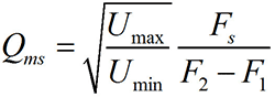
The electrical quality factor (Qes) is found using this formula.

Finally, we determine the total electromechanical quality factor (Qts) using this formula.

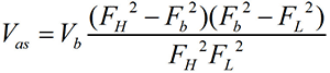
1.1.2.3. Determination of the equivalent volume (Vas) of a loudspeaker.
To determine the exact equivalent volume, we will need a pre-fabricated, durable, sealed bass reflex box with a hole for our speaker.

The volume of the box depends on the diameter of the speaker, and is selected according to this table.

We fix the speaker to the box and connect it to the circuit described above (Fig. 9). Again, open the NCH Tone Generator program, set the initial frequency to 10Hz and using the “+” button, we begin to smoothly, in 1Hz steps, increase the generator frequency to 500Hz. At the same time, we look at the voltmeter value, which will again begin to increase to the frequency FL, then decrease, reaching a minimum point at the bass reflex tuning frequency (Fb), increase again and reach the maximum point at the frequency FH, then decrease and slowly increase again. The graph of voltage versus signal frequency has the shape of a Bactrian camel.

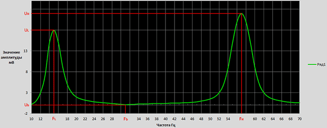

And finally, we find the equivalent volume (Vas) using this formula (where Vb is the volume of the box with the bass reflex).
We repeat all our measurements 3-5 times and take the arithmetic average of all parameters. For example, if we received the Fs values respectively 30.45Hz 30.75Hz 30.55Hz 30.6Hz 30.8Hz, then we take (30.45+30.75+30.55+30.6+30.8)/5= 30.63Hz.
As a result of all my measurements, I received the following parameters for my speaker:
- Fs=30.75 Hz
- Qts=0.365
- Vas=112.9≈113 l
1.2.Modeling and calculation of the subwoofer body (box) using the JBL Speakershop program.
There are several options for acoustic designs, of which the following options are the most common.
- Vented box with bass reflex,
- Band-pass 4th, 6th and 8th order,
- Passive radiator - box with a passive radiator,
- Closed box - closed box.

The type of acoustic design is selected based on the Thiel-Small parameters of the loudspeaker. If Fs/Qts<50, то такой громкоговоритель можно использовать исключительно в закрытом оформлении, если Fs/Qts>100, then exclusively in Vented box or Band-pass or Closed box. If 50
First, download and install the program. This program is written for Windows XP and does not work on Windows 7. To make the program work on Windows 7, you need to download and install virtual machine Windows Virtual PC-XP Mode (you can download it from the official Microsoft website), and run the JBL Speakershop installation through it. You also need to open JBL Speakershop through a virtual machine. After opening the program we see this interface.

Click “Loudspeaker” and select “Parameters--minimum”, in the open window we write, respectively, the value of the resonant frequency (Fs), the value of the equivalent volume (Vas), the value of the total electromechanical quality factor (Qts) and click “Accept”.

In this case, the program will offer two optimal (with the most even frequency response) options, one in a closed design (Closed box), the other in a Vented box (box with a bass reflex). Click “plot” (both in the Vented box area and in the Closed box area) and look at the frequency response graph. We choose the design whose frequency response most suits our requirements.

In my case, this is a Vented box, since at low frequencies (20-50Hz) the Closed box has a much greater amplitude decay than the Vented box (Figure above).
If the optimal volume of the box suits you, then you can build a box with that volume and enjoy the sound of the subwoofer. If not (if the volumes are too large), then you need to set your volume (the closer to the optimal volume, the better) and calculate the optimal tuning frequency of the bass reflex.

To do this, in the Vented box area, click “Custom”, in the window that opens, write your box volume, click “Optimum Fb” (in this case, the program will calculate the optimal tuning frequency of the bass reflex, at which the frequency response of the acoustic design will be the most linear) and then “Accept”.

Click “Box” and select “Vent...”, in the window that opens, in the “Custom” area, write the diameter of the pipe (Dv), which we will use as a bass reflex. If we use two bass reflexes, then we put a dot on “Area” and write the total cross-sectional area of the pipes.


Click “Accept” and in the “Custom” area on the Lv line the length of the bass reflex pipe will appear. Now that we know the internal volume of the box, the diameter and length of the bass reflex pipe, we can safely move on to designing the acoustic design, but if you really want to know the optimal aspect ratio of the box, you can click “Box” and select “Dimensions...”.

1.3.Design of the subwoofer housing (box)
To obtain high-quality sound, it is necessary not only to correctly calculate, but also to carefully manufacture the acoustic design housing. After determining the internal volume of the box, the length and diameter of the bass reflex pipe, you can safely proceed to the manufacture of the subwoofer enclosure. The material of the box must be strong and rigid enough. The most suitable material for high-power acoustic cabinets is twenty-millimeter MDF. The walls of the box are attached to each other with self-tapping screws, and the gaps between them are smeared with sealant or silicone. After making the box, holes are made for the handles, and the finishing of the outer surface begins. All unevenness will be smoothed out using putty or epoxy resin (I add a little PVA glue to the putty, which prevents cracks from appearing over time and reduces the level of vibrations). After the putty has dried, the surfaces must be sanded until perfectly smooth walls are obtained. The finished box can be either painted or covered with self-adhesive decorative film, or simply glued with thick fabric. From the inside, a sound-absorbing material consisting of cotton wool and gauze is glued to the walls of the box (in my case I glued batting). As a bass reflex, you can use a plastic sewer pipe or a paper rod from different rolls, as well as a ready-made bass reflex that can be bought at almost any music store.
The active subwoofer housing consists of two compartments. The first compartment houses the loudspeaker itself, and the second contains the entire electrical part (signal conditioner, amplifier, power supply......). In my case, I placed the adder unit and filter unit in a separate compartment from the power amplifier unit, power supply and cooling unit. From the inside, I glued foil to the walls of the adder block and filter block compartment, which I connected to ground (GND). The foil prevents exposure to external fields and reduces noise levels.


If you use my printed circuit boards, these compartments should have the following dimensions.


2. Electrical part of the active subwoofer
Let's move on to the electrical part of the active subwoofer. The general diagram and principle of operation of the device is represented by this diagram.

The device consists of four blocks assembled on separate printed circuit boards.
- Block of adders (Summators),
- Filter block (Subwoofer driver),
- Power amplifier block,
- Power supply and cooling unit (Heatsink fun).
At first sound signal enters the adder block (Summators), where the signals of the right and left channels are summed. Then it goes to the filter block (Subwoofer driver), where the subwoofer signal is formed, which includes a volume control, subsonic filter (infra low-pass filter), bass booster (increasing the volume at a certain frequency) and Crossover (low-pass filter). After formation, the signal enters the power amplifier block, and then into the loudspeaker.
Let's discuss these blocks separately.
2.1. Block of adders (Summators)
2.1.1.Scheme
First, let's look at the adder circuit shown in the figure below.
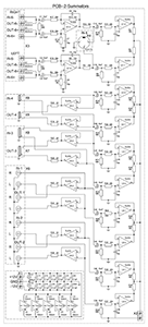
The sound signal from external devices (computer, CD player........) enters the adder block, which has 6 stereo inputs. 5 of them are ordinary linear inputs, differing from each other only in the type of connector. And the sixth is a high-voltage input to which you can connect the output of speakers (for example, a stereo or car radio that does not have a line output). Each input has a separate operational amplifier combiner that biases the signals of the right and left channels, which prevents the audio signal from one external device from entering another, while making it possible to simultaneously connect several external devices to the subwoofer. There are also outputs (5 outputs, the 6th simply didn’t fit on the board, so I didn’t install it), which make it possible to supply the same signal that goes into the subwoofer to the input of a wideband stereo system. This is very convenient when the sound source has only one output.


2.1.2.Components
TL074 (5 pcs.) were used as operational amplifiers. Resistors are rated for power of 0.25W or higher (resistance ratings are shown in the diagram). All electrolytic capacitors have a voltage rating of 25 Volts or higher (capacitance ratings are shown in the diagram). As non-polar capacitors, you can use ceramic or film capacitors (preferably film), but if you really want to, you can use special audio capacitors (capacitors designed for use in high-quality audio systems). Chokes in the power supply circuit of operational amplifiers are designed to suppress “noise” coming from the power supply. Coils L1-L4 contain 20 turns wound with copper wire with a diameter of 0.7 mm on a gel pen rod (3 mm). Also used are RCA, 3.5mm audio jack, 6.35mm audio jack, XLR, WP-8 connectors.

2.1.3.PCB


The printed circuit board is made using . After soldering the parts, the printed circuit board should be coated to avoid oxidation of the copper.
2.1.4. Photo of the finished adder block


The adder unit is powered from a bipolar power supply with a voltage of ±12V. The input impedance is 33kOhm.
2.2.Filter block (Subwoofer driver)
2.2.1.Scheme
Consider the subwoofer driver circuit shown in the figure below.

The summed signal from the adder block enters the filter block, which consists of the following parts:
- Volume regulator,
- Infra-low frequency filter (subsonic filter),
- Bass booster of a certain frequency (bass booster),
- Low pass filter (crossover).
Volume control occurs at two levels. The first is when the signal enters the filter block, which reduces the level of its own “noise” of the adder block, the second is when the signal outputs from the filter block, which reduces the level of its own “noise” of the filter block. The volume is adjusted using variable resistor VR3. After the first level of volume control, the signal enters the so-called “bass booster,” which is a device that increases the amplitude of signals of a certain frequency. That is, if the bass booster tuning frequency is set to, for example, 44Hz, and the gain level is 14dB, then the frequency response looks like this ( Row1).

Row2- tuning frequency=44Hz, gain level=9dB,
Row3- tuning frequency=44Hz, gain level=2dB,
Row4- tuning frequency=33Hz, gain level=3dB,
Row5- tuning frequency=61Hz, gain level=6dB.
The bass booster tuning frequency is set using variable resistor VR5 (within 25...125Hz), and the gain level with resistor VR4 (within 0...+14dB). After the bass booster, the signal enters the subsonic filter, which is a filter that cuts off unwanted, ultra-low signals that are no longer audible to humans, but can greatly overload the amplifier, thereby reducing the actual output power of the system. The filter cutoff frequency is adjusted using variable resistor VR2 within the range of 10...80Hz. If, for example, the cutoff frequency is inserted at 25Hz, then the frequency response has the following form.
After the infra-low-pass filter, the signal goes to a low-pass filter (crossover), which cuts off the upper frequencies (mid + high) that are unnecessary for the subwoofer. The cutoff frequency is adjusted using a variable resistor VR1 within the range of 30…250Hz. The attenuation slope is 12 dB/octave. The frequency response looks like this (at a cutoff frequency of 70Hz).
2.2.2.Components
TL074 (2 pcs.), TL072 (1 pc.) and NE5532 (1 pc.) were used as operational amplifiers. Resistors are rated for power of 0.25W or higher (resistance ratings are shown in the diagram). All electrolytic capacitors have a voltage rating of 25 Volts or higher (capacitance ratings are shown in the diagram). Ceramic or film capacitors (preferably film) can be used as non-polar capacitors. Chokes in the power supply circuit of operational amplifiers are designed to suppress “noise” coming from the power supply. Three double (50kOhm-2pcs., 20kOhm-1pc.) and two quadruple variable (50kOhm-6pcs.) resistors were also used. Two double ones can be used as quad variable resistors.
2.2.3.PCB

PCB files in *.lay and *.pdf formats can be downloaded at the end of the article.
2.2.4.Photo of the finished filter block


The filter unit is powered from a bipolar power supply with a voltage of ±12V.
2.3.Power amplifier block.
2.3.1.Scheme
The power amplifier is an Anthony Holton amplifier with field-effect transistors in the output stage. There are a lot of articles describing the operating principle, assembly and configuration of the amplifier on the Internet. Therefore, I will limit myself to attaching the schematic and my version of the printed circuit board.

2.3.2.PCB


PCB files in *.lay and *.pdf formats can be downloaded at the end of the article. The power amplifier unit is powered from a bipolar power supply with a voltage of ±50…63V. The output power of the amplifier depends on the supply voltage and the number of pairs of field-effect transistors (IRFP240+IRFP9240) in the output stage.
2.4. Power supply and cooling unit (Power supply)
2.4.1.Scheme
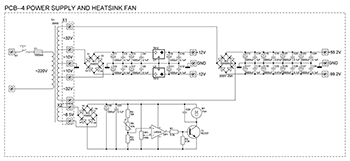
2.4.2.Components
As a power transformer, you can use either a ready-made or a home-made transformer with a power of approximately 200 W. The voltages of the secondary windings are shown in the diagram.


The Br2 diode bridge is designed for a current of 25A. Capacitors C1…C12,C29…C31 must have a rated voltage of 25V. Capacitors C13...C28 must have a rated voltage of 63V (for supply voltages below 60V), or 100V (for supply voltages above 60V). It is better to use film capacitors as non-polar capacitors. All resistors are rated for 0.25W power. Thermistor R5 is coated with thermal paste and attached to the amplifier's heatsink. The operating voltage of the fan is 12V.
2.4.3.PCB

PCB files in *.lay and *.pdf formats can be downloaded at the end of the article.
3.The final stage of subwoofer assembly


List of radioelements
| Designation | Type | Denomination | Quantity | Note | Shop | My notepad | |
|---|---|---|---|---|---|---|---|
| U1-U5 | Operational amplifier | TL074 | 5 | To notepad | |||
| C1-C4, C15, C16, C25-C27, C29, C39-C42 | 10 µF | 14 | To notepad | ||||
| C5-C10, C23, C24, C28, C30, C35-C38 | Capacitor | 33 pF | 14 | To notepad | |||
| C11-C14, C19-C22, C31-C34 | Capacitor | 0.1 µF | 12 | To notepad | |||
| C17, C18 | Electrolytic capacitor | 470 µF | 2 | To notepad | |||
| R1, R2 | Resistor | 390 Ohm | 2 | To notepad | |||
| R3, R12 | Resistor | 15 kOhm | 2 | To notepad | |||
| R4, R16-R18 | Resistor | 20 kOhm | 4 | To notepad | |||
| R5, R13-R15 | Resistor | 13 kOhm | 4 | To notepad | |||
| R6, R10, R23, R24, R31, R33, R40, R41, R46, R47 | Resistor | 68 kOhm | 10 | To notepad | |||
| R7, R11, R21, R22, R32, R34, R37, R38, R45, R48 | Resistor | 22 kOhm | 10 | To notepad | |||
| R8, R9, R25, R26, R29, R30, R39, R42, R49, R50 | Resistor | 10 kOhm | 10 | To notepad | |||
| R19, R20, R27, R28, R35, R36, R43, R44 | Resistor | 22 Ohm | 8 | To notepad | |||
| L1-L4 | Inductor | 20x3mm | 4 | 20 turns, wire 0.7mm, frame 3mm | To notepad | ||
| L5-L13 | Inductor | 100 mH | 10 | To notepad | |||
| Filter block | |||||||
| U1 | Operational amplifier | TL072 | 1 | To notepad | |||
| U2, U4 | Operational amplifier | TL074 | 2 | To notepad | |||
| U3 | Operational amplifier | NE5532 | 1 | To notepad | |||
| C1-C5, C7-C10, C15-C17, C20, C23 | Capacitor | 0.1 µF | 14 | To notepad | |||
| C6 | Capacitor | 15 nF | 1 | To notepad | |||
| C11-C14 | Capacitor | 0.33 µF | 4 | To notepad | |||
| C21, C22 | Capacitor | 82 nF | 2 | To notepad | |||
| VR1-VR3, VR5 | Variable resistor | 50 kOhm | 4 | To notepad | |||
| VR4 | Variable resistor | 20 kOhm | 1 | To notepad | |||
| R1, R3, R4, R6 | Resistor | 6.8 kOhm | 4 | To notepad | |||
| R2, R10, R11, R13, R14 | Resistor | 4.7 kOhm | 5 | To notepad | |||
| R5, R8 | Resistor | 10 kOhm | 2 | To notepad | |||
| R7, R9 | Resistor | 18 kOhm | 2 | To notepad | |||
| R12, R15-R17, R20, R22, R26, R27 | Resistor | 2 kOhm | 8 | To notepad | |||
| R18, R25 | Resistor | 3.6 kOhm | 2 | To notepad | |||
| R19, R21 | Resistor | 1.5 kOhm | 2 | To notepad | |||
| R23, R24, R30, R31, R33 | Resistor | 20 kOhm | 5 | To notepad | |||
| R28 | Resistor | 13 kOhm | 1 | To notepad | |||
| R29 | Resistor | 36 kOhm | 1 | To notepad | |||
| R32 | Resistor | 75 kOhm | 1 | To notepad | |||
| R34, R35 | Resistor | 15 kOhm | 2 | To notepad | |||
| L1-L8 | Inductor | 100 mH | 1 | To notepad | |||
| Power amplifier block | |||||||
| T1-T4 | Bipolar transistor | 2N5551 | 4 | To notepad | |||
| T5, T9, T11, T12 | Bipolar transistor | MJE340 | 4 | To notepad | |||
| T7, T8, T10 | Bipolar transistor | MJE350 | 3 | To notepad | |||
| T13, T15, T17 | MOSFET transistor | IRFP240 | 3 | To notepad | |||
| T14, T16, T18 | MOSFET transistor | IRFP9240 | 3 | To notepad | |||
| D1, D2, D5, D7 | Rectifier diode | 1N4148 | 4 | To notepad | |||
| D3, D4, D6 | Zener diode | 1N4742 | 3 | To notepad | |||
| D8, D9 | Rectifier diode | 1N4007 | 2 | ||||
The main thing is to have a high-quality low-frequency speaker on hand, preferably an imported one, but in extreme cases, you can use Soviet-made dynamic heads, for example 25GD from S-30 radio speakers. Since our goal is to collect only High Quality, then we will abandon the stereo amplifier and use the TDA2050 microcircuit.

This amplifier is of fairly high quality and has a decent output power of 32 watts. The article does not give the dimensions of the box, since it is important to maintain a displacement of 7 liters, and let the design be to your taste and individual design. Chipboard boards with a thickness of 0.5 mm were used, the phase inverter was designed for 35 hertz. Subwoofer circuit:

The amplifier is attached to the heat sink. As can be seen from the connection diagram, output diodes are excluded from it, since the TDA2050 has these diodes built into the microchip and there is no point in installing additional ones. The passive low pass filter circuit is shown below. The power supply is a transformer with a power of 50-70 watts, on which two windings with a voltage of 10-12 volts each and a current of at least 2 amperes are wound. You can also make a transformer yourself. To do this, we take any network transformer with a power of 50 watts or more and wind a secondary winding on it, which contains 60 turns with a tap from the middle. Winding is done with wire with a diameter of 1 - 1.5 mm. The power supply diagram is shown below.

The most important thing in designing subwoofers is maintaining tightness, so after completing assembly, you need to carefully place everything in the box, carefully attaching the power amplifier and transformer to the wall of the box, then close the subwoofer cover with PVA glue and self-tapping screws. The glue then needs time to dry, and after a few hours the subwoofer is ready for use.
It is better to make the volume control and input jack at the back. You can connect anything to a subwoofer - a computer, TV, DVD player and even mobile phone; and remember - if we connect an amplified sound signal to the subwoofer, for example from a laptop or TV, then it plays much louder, since there is no additional amplifier in the low-pass filter and there are large losses. That's all - listen to your health! AKA