DIY tube amplifier step by step instructions. Tube amplifier. Circuits with transistors
Today we have useful homemade product for connoisseurs of good sound: a high-quality hand-made tube amplifier
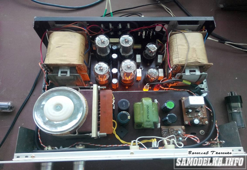
Hello!
I decided to assemble a push-pull tube amplifier (my hands were really itching) from the parts I had accumulated over a long time: housing, lamps, sockets for them, transformers, etc.
I must say that I got all this stuff for free (you mean free of charge) and the cost of my new project will be 0.00 hryvnia, and if I need to buy something in addition, I’ll buy it for rubles (since I started my project in Ukraine, and I’ll finish already in Russia).
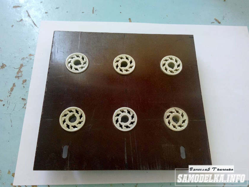
I'll start the description with the body.

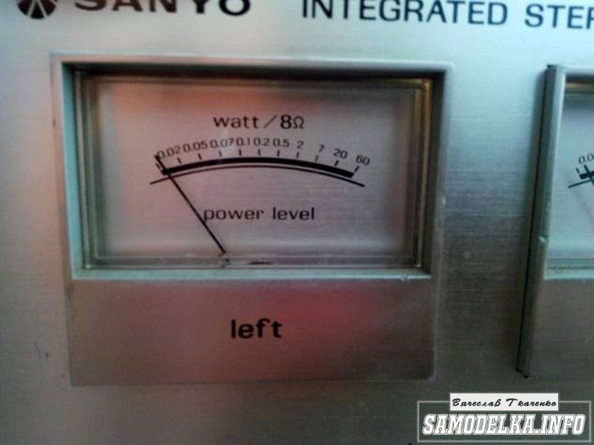
Once upon a time it was, apparently, a good amplifier from SANYO model DCA 411.
But I didn’t have a chance to listen to it because I got it in a terribly dirty and non-working state, it was dug up beyond repair and the burnt 110 V power supply (Japanese, probably) smoked all the insides. Instead of the original final stage microcircuits, there are some snot from Soviet transistors (this is a photo from the Internet of a good example). In short, I gutted it all out and began to think. So, I couldn’t think of anything better than stuffing a lamp there (there’s quite a lot of space there).

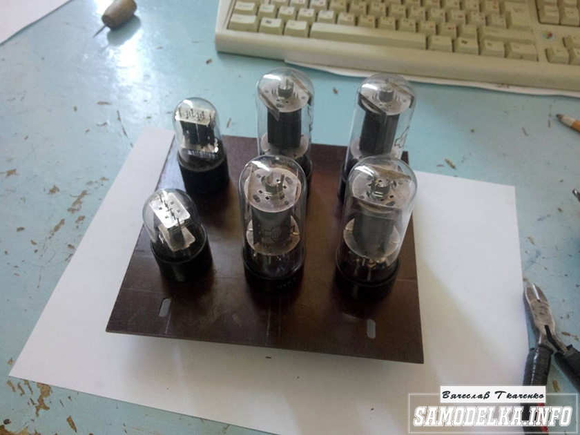
Decision is made. Now we need to decide on the scheme and details. I have a sufficient number of 6p3s and 6n9s lamps.
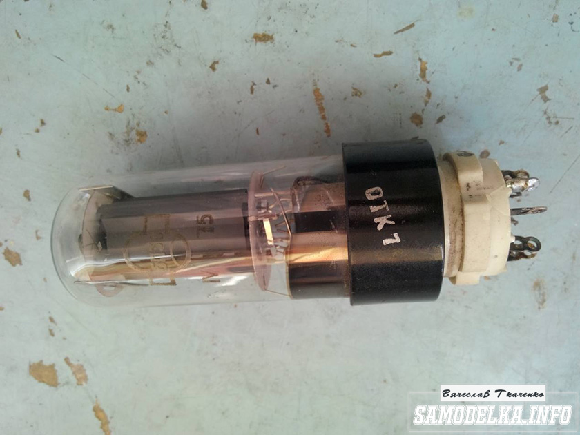


Due to the fact that I had already assembled a single-cycle amplifier for 6p3s, I wanted more power and, having rummaged through the Internet, I chose this push-pull amplifier circuit for 6p3s.
Circuit of a homemade tube amplifier (ULF)

The diagram is taken from the website heavil.ru
I must say that the scheme is probably not the best, but due to its relative simplicity and availability of parts, I decided to stick with it. Output transformer (an important figure in the plot).
It was decided to use the “legendary” TS-180 as output transformers. Don’t throw stones right away (save them for the end of the article :)) I myself have deep doubts about this decision, but given my desire not to spend a penny on this project, I will continue.
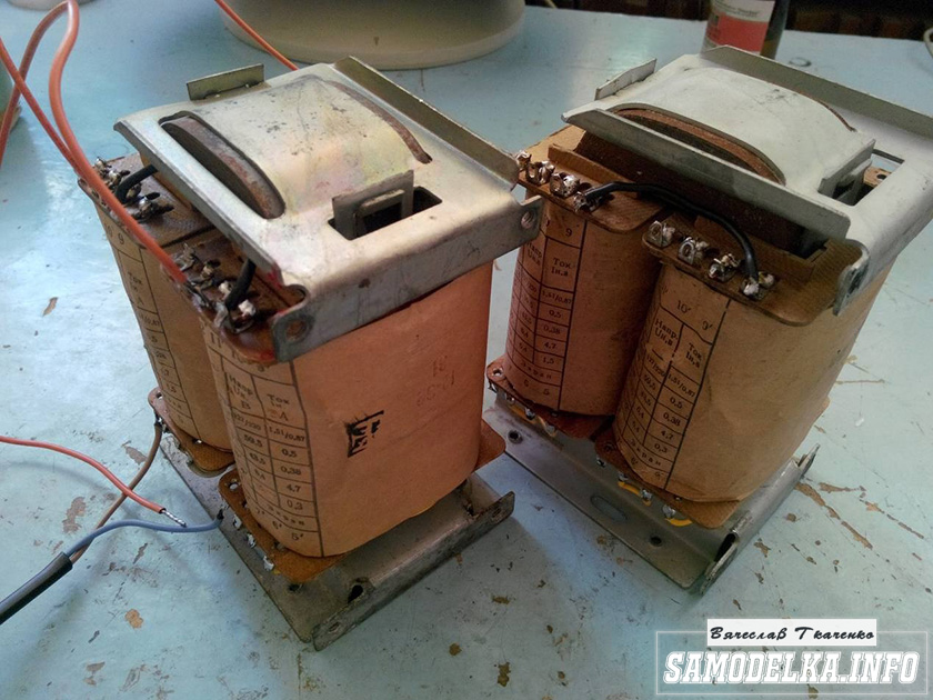
I connected the trance outputs for my case like this.
(8)—(7)(6)—(5)(2)—(1)(1′)—(2′)(5′)—(6′)(7′)—(8′) primary
(10)—(9)(9′)—(10′) secondary
anode voltage is applied to the connection of pins 1 and 1′, 8 and 8′ to the anodes of the lamps.
10 and 10′ per speaker. (I didn’t come up with this myself, I found it on the Internet). To dispel the fog of pessimism, I decided to check the frequency response of the transformer by eye. To do this, I quickly assembled such a stand.

In the photo there is a GZ-102 generator, a BEAG APT-100 amplifier (100V-100W), an S1-65 oscilloscope, a 4 Ohm load equivalent (100W), and the transformer itself. By the way, there is a .
I set it to 1000 Hz with a swing of 80 (approximately) volts and record the voltage on the oscilloscope screen (about 2 V). Next, I increase the frequency and wait until the voltage on the trance secondary starts to drop. I do the same thing in the direction of decreasing the frequency.
The result, I must say, pleased me: the frequency response is almost linear in the range from 30 Hz to 16 kHz, well, I thought it would be much worse. By the way, the BEAG APT-100 amplifier has a step-up transformer at the output and its frequency response may also not be ideal.
Now you can collect everything in a heap into a case with a clear conscience. There is an idea to do the installation and layout inside in the best traditions of so-called modding (minimum wires in sight) and it would also be nice to have LED backlighting like in industrial copies.
Power supply for a homemade tube amplifier.
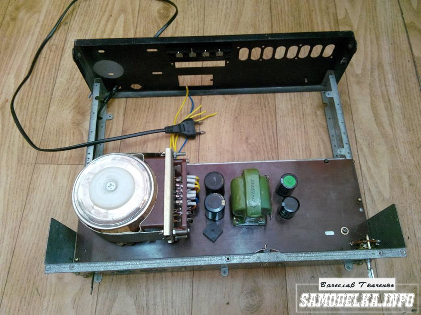
I'll start the assembly and at the same time describe it. The heart of the power supply (and of the entire amplifier, probably) will be the TST-143 toroidal transformer, which I once (4 years ago) tore out of some tube generator right as it was being taken to a landfill. Unfortunately, I didn’t manage to do anything else. It’s a pity for such a generator, but maybe it was still working or could have been repaired... Okay, I digress. Here he is my security officer.

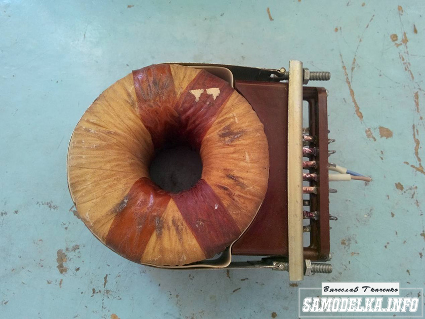
Of course, I found a diagram for it on the Internet.

The rectifier will be on a diode bridge with a filter on the inductor for anode power. And 12 volts to power the backlight and anode voltage. This is the throttle I have.

Its inductance was 5 henry (according to the device), which is quite enough for good filtration. And the diode bridge was found like this.

Its name is BR1010. (10 amps 1000 volts). I'm starting to cut out the amplifier. I think it will be something like this.
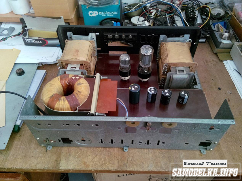
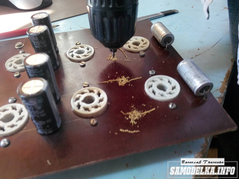
I mark and cut holes in the PCB for the sockets for the light bulbs.


It turns out well :) I like everything so far.

This way and that way. drill and saw :)
Something began to emerge.

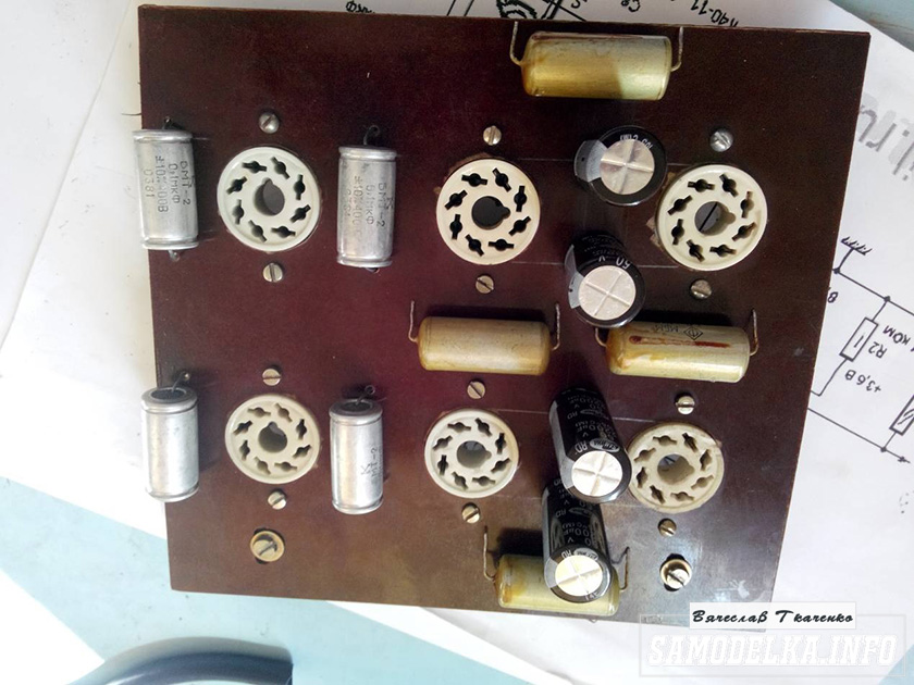
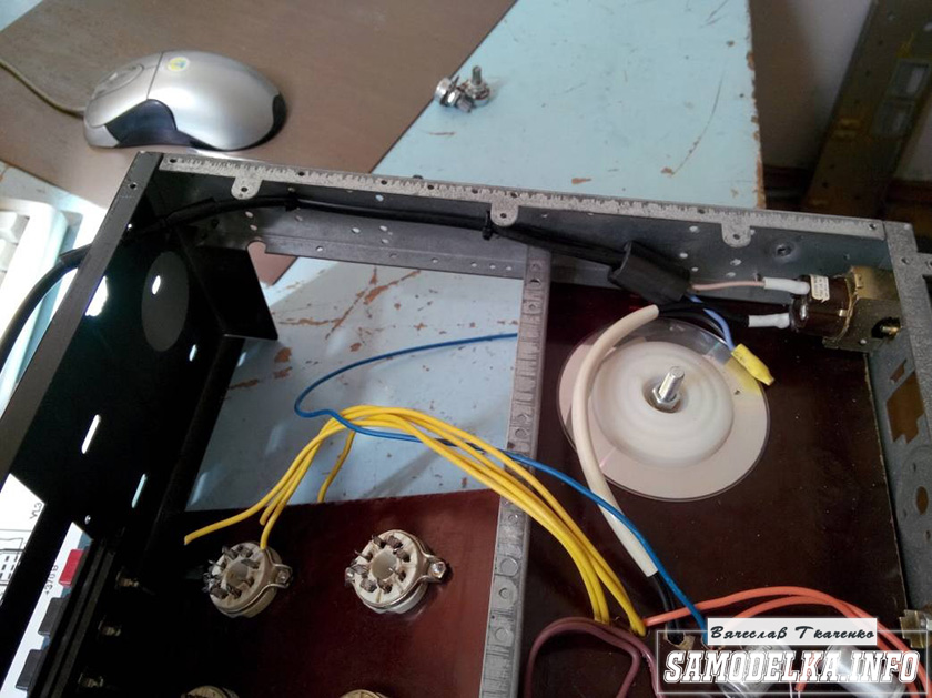
I found a fluoroplastic wire in old supplies and immediately all the alternatives and compromises regarding the wire for installation disappeared without a trace :) .


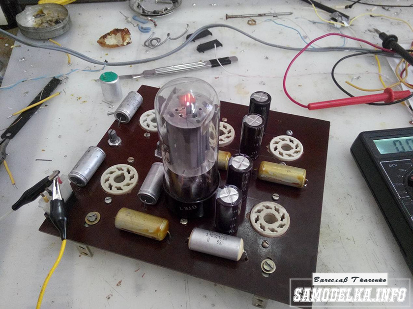
This is how the installation turned out. Everything seems to be “kosher”, the incandescence is intertwined, the ground is practically at one point. Should work.

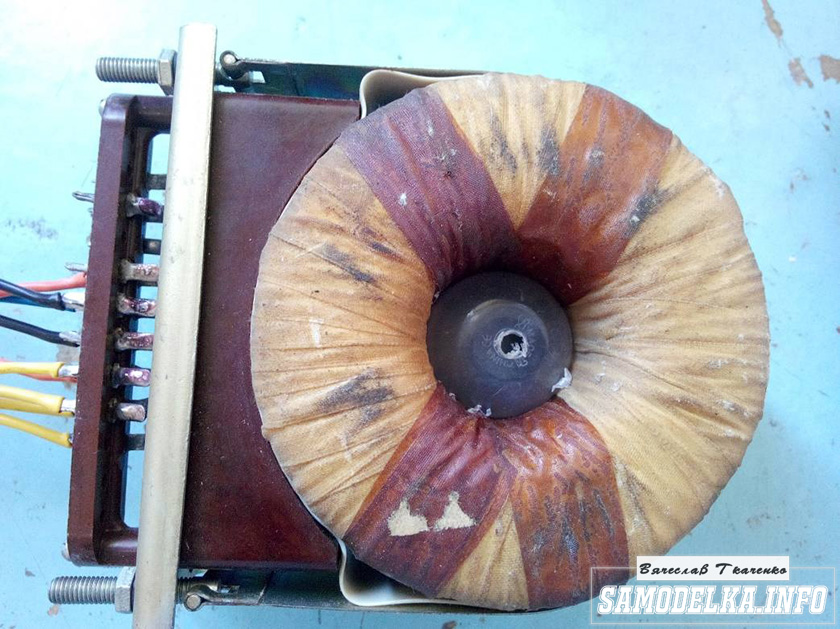
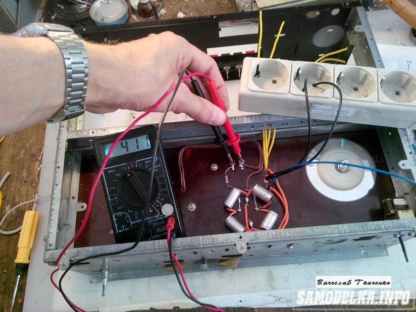
It's time to fence in food. After checking and testing all the output windings of the trans, I soldered all the necessary wires to it and began installing it according to the accepted plan.

As you know, in our life it’s not easy to go anywhere without improvised materials: this is how the Kinder Surprise container came in handy.
And a Nescafe lid and an old CD
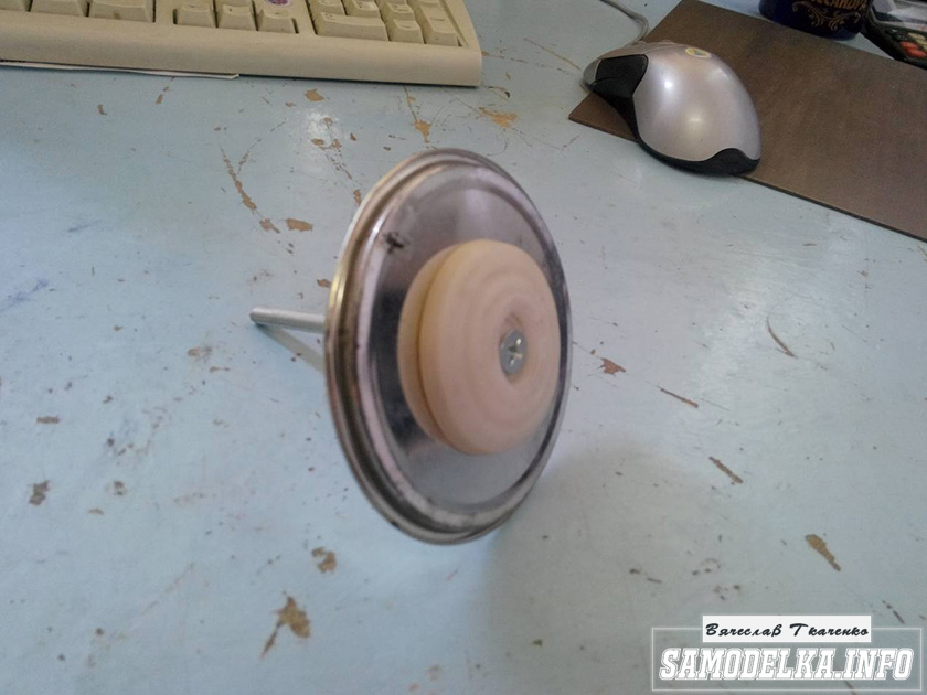


I tore out the circuit boards of TVs and monitors. All containers are at least 400 volts (I know that I should have more, but I don’t want to buy them).
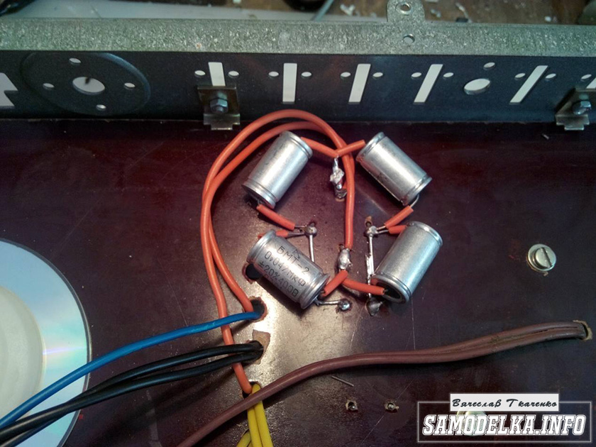
I bridge the bridge with containers (whatever were on hand, I’ll probably change them later)
It’s a bit much, but oh well, it will sag under load :)
I use the standard power switch from the amplifier (clear and soft).
We're done with that. It turned out well :)
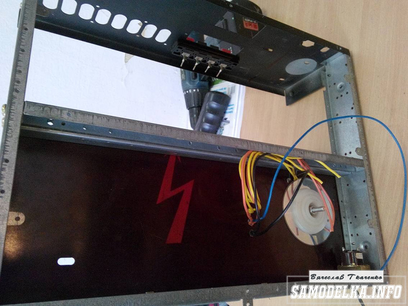
Backlight for tube amplifier housing.
To implement the backlight, an LED strip was purchased.

And installed in the housing as follows.

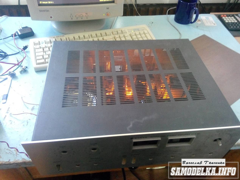
Now the glow of the amplifier will be visible during the daytime. To power the backlight, I will make a separate rectifier with a stabilizer on some KRKEN-like microcircuit (which I can find in the trash), from which I plan to power the anode voltage supply delay circuit.
Delay relay.
Having rummaged through the bins of my homeland, I found this completely untouched thing.
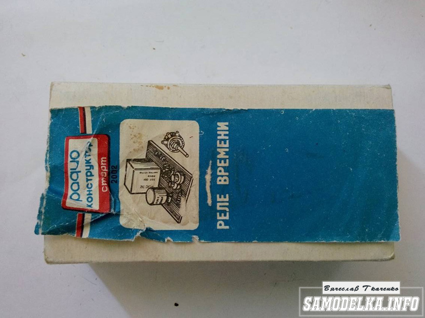
This is a radio time relay designer for a photo enlarger.


We collect, check, try on.

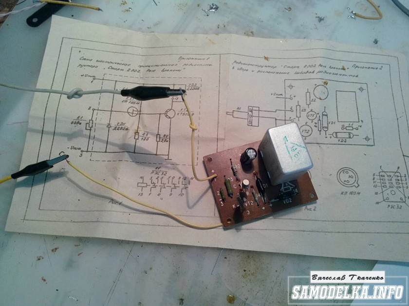

I set the response time to about 40 seconds, and replaced the variable resistor with a constant one. The matter is coming to an end. All that remains is to put everything together, install the face, indicators and regulators.
Regulators (input variables)
They say the sound quality can greatly depend on them. In short, I installed these

Dual 100 kOhm. Since I have two of them, I decided to parallel the pins, thereby obtaining 50 kOhm and increased resistance to wheezing :)
Indicators.
I used standard indicators, with standard backlighting
I mercilessly copied the connection diagram from the original board and used it as well.

This is what I ended up with.


When checking the power, the amplifier demonstrated an output voltage of 10 volts of an undistorted sine wave with a frequency of 1000 Hz into a 4 ohm load (25 watts) equally across channels, which was pleasing :)
When listening, the sound was crystal clear without background and dust, as they say, but too monitory, or what? beautiful, but flat.
I naively believed that he would play without timbres, but...
Using a software equalizer, we managed to get a very beautiful sound that everyone liked. Thank you all very much!!!
Author of the article “homemade tube amplifier with your own hands” Vyacheslav Tkachenko.
You may be interested in the following materials.
So. As I already wrote, I have been struggling for about 3 months to find the best circuit and the most interesting sounding tube amplifier. The goal is to make a tube amplifier with your own hands with the least loss, both financial and in sound quality. I tried several tubes of different types and manufacturers. The first amplifier I assembled with my own hands was a 2-tube 6p6s and 6n9s. The 6p6s lamp (but it would be more correct to assemble an 18-watt marshal on lamps such as 6p14p, 6p14p-ev, 6p43p and what about the original EL84) I really liked the sound of the most optimal option for a guitar. 6n9s is a double triode, so in order to save space we are replacing it with a 6n2p more modern brother. After playing for a month on a single-ended amplifier, I still realized that it was not. NOT ENOUGH! You need to stir up something more and louder. I read several dozen articles from forums, I understood the principle by which they work. I first tried a circuit with 3 lamps and then finally returned to a 4-lamp Marshall 18 Watt circuit.
Marshall 18 Watt Circuit
The circuits differ only in tone blocks, I personally did the same as on the bottom one, but I leave the choice up to you.
(to view in large size follow the link to the photo and select "in a different size > original")

The presented schemes are Lite versions
In general, the scheme is as old as time, let's say a classic of musical sound. One of the most common schemes of the famous company. This amplifier even has its own website with hundreds of replica options. And so, the process of purchasing and selecting parts began. At that time I had a couple of 6p6s lamps and a couple of 6n2p lamps before I bought the pads. Then I started looking for transformers. You can order the output transformer in the online store from Erasov, or try to find something similar on the breakers. I found a transformer on the radio market in Tsaritsino. I used TPP 245-127/220-50, the primary windings were just right for splitting into
half-cycles from the lamps, and the secondary ones are 15-16 and 17-18, that is, 10+10 volt
windings

To reduce noise, it is recommended to install a small choke immediately after the diode bridge. I used D22, although it has a small current, nothing fatal happened to it. Lamps can be ordered either in the same Erasov or in the online store http://www.istok2.com/. We either buy all the related parts where we can buy them, or we assemble them ourselves.
Next we make the chassis. The chassis is the basis on which all installation is done. You can buy it, which actually costs about $100, but can be made from an old computer case. Which is exactly what I did. The old AT case has a top cover and both walls are a single bent sheet. We measure out how much we need and saw off.

" " on Yandex.Photos

" " on Yandex.Photos

I made the power board on a PCB.

Don't forget about currents! So 6.3 volts would be enough for all the lamps. I had to buy a 4*6.3 transformer separately in order to power all 4 lamps. Also, don’t forget to shunt 6.3 volts to common “-”. Another recommendation for power supply I can only say is that, if possible, try to split the heat and 300V into different toggle switches. Since it is better to supply voltage to a warm lamp.


on Yandex.Photos
At first I was lazy and soldered it basically haphazardly. Everything is completely scary, the fog is buzzing, in short, chaos. So it’s better to do it right away and honestly. But at this stage it is recommended to decide where you will have what. And for purely practical reasons, I can advise placing the lamps on the opposite side from the front panel. AND DON'T AT ANY TIME!!! case, do not paint if you are not sure. I'll have to disassemble everything and repaint the chassis!


The board can be made from anything, the main thing is that everything is clean and neat. and with the shortest distance of wires through which the signal flows. And just try to concentrate the power in one place and run all the wires along one bundle.
If we have collected everything and everything works for us, then it should look something like this.
(the article is not finished and will be added to, painting is ahead, assembling the head housing and cabinet, fine tuning and samples!)

Again, a recommendation: before drilling holes, think carefully or try on your knees what configuration you will end up with. To attach the chassis to the body, 2 boards were screwed to the side walls. DIY amplifier he actually assumes that you will do and redo everything 150 times if you don’t think everything through from the beginning.
Now a little about routing the wires. From my recommendations... immediately after the sockets, place a resistor on the common (-) 1 Mohm, mount it directly on the lamp legs, the wire from the sockets is strictly shielded.
The 6.3 volt filament wires must be woven into a tight braid (twisted pair).

We bring all common wires (ground) to one point, this installation is called a star. We take the wire from any old choke with a cross-section of 0.75, if you find it, the insulating wire should be made of varnish-kini, but in principle you can use any cambric without any problems.

Well, as I said, the chassis will have to be repainted.
In the end, I left only the master volume, and simply threw away all the other tinsel. 
Thanks to all my friends for your help and information. I give a few more links to articles from. At http://rumapucm.ya.ru the scheme was completely redesigned by me and from Light it was made even lighter.
Really awesome amplifier Marshall 18 watt Unfortunately, I did not assemble the original circuit, but replaced the output lamps with actual ones. Of course, this radically changes the sound, it’s still real Marshal 18 the amplifier is considered to be 6p14p (EL84)
I think that someday I’ll work on this project and build myself a Christmas tree marshal :)
A person whom I once helped in searching for radio tubes contacted me. This time he needed help in repairing the amplifier that he had assembled using these tubes: a strong hum appeared in one channel, which he could not overcome.
Here we need to say a few words about the customer himself - he is a brutal guy with a biker look, with a thick black beard and tattoos, and at the same time a kind-hearted man. His occupation, which matches his appearance, is repairing motorcycles. In electronics, he, in his own words, understands nothing. Everyone wouldn’t “understand” that they could assemble their own tube amplifiers, but oh well)
I agreed to help him, and soon he brought me this miracle:
The amplifier housing turned out to be welded from a 2-mm steel sheet, which was then further aged and coated with copper. Fortunately, photographs of the work process have been preserved, so with the permission of the author I will share them:

All work was done by hand using a grinder, drill, files and, of course, a welding machine.


The design intricately combines modern elements and parts from Soviet radio technology.

I really liked the textured coating of the case, and I even seriously thought about whether I should use something similar in my own projects.

In general, the amplifier was left to me with a request to repair it as soon as possible. I connected it to the speakers and was convinced that there was a strong hum in one channel. As you know, electronics is the science of contacts, so something is probably unsoldered somewhere, or, conversely, shorted out. This can be fixed quite quickly, I thought naively.
When I first looked into the "basement", at first glance everything looked good - at least for an amplifier made by an absolute beginner. The author simply took and installed two low-frequency amplifier boards from the Ural-112 radio radio inside.

But since the location of the lamps and transformers did not suit him, he desoldered them and carefully built up all the connections with wires.

Unfortunately, lamp technology does not tolerate such installation: long wires, repeatedly intertwined and crossing each other, collect all imaginable noise and interference. In addition, the author used a single-color MGTF wire, and it was almost impossible to figure out what went where. And there was no point in keeping the original boards: their only advantage, which was that they could be installed “as is” and save time and effort, was lost, and only disadvantages remained.

Let's say, in the power part, obsolete selenium rectifiers and huge resistors of the BC type, which were used only in the power circuit of the high-frequency radio unit (R5, R1 and R8), were in vain taking up space. But the resistive divider R3-R4, which was supposed to supply a small positive voltage to the midpoint of the filament winding to reduce the noise level, was lost during the transfer process.

It is worth noting that this “not versed in electronics” person himself (albeit using a ready-made circuit) soldered the display unit on “magic eye” lamps, and even with a separate amplifier on a 6N2P lamp, which made it independent of the output level volume. True, huge 2-watt resistors were used (although 0.25-watt ones would have been enough) - he installed them according to the principle “too much is not too little” so that there would definitely not be overheating. Here is such an amazing combination of ingenuity, direct hands and, moreover, a complete lack of experience, leading to slightly curious, but still impressive results.

Acting on a whim, the author made two channels of the amplifier completely mirrored - each with its own power transformer. This also turned out to be redundant, since now there was no need to power the lamps responsible for radio reception. The second transformer only got in the way, and even made a loud noise, because its plates had become loose over time, and the design did not allow them to be tightened securely.
In general, I realized that there is no quick repair here, and the amplifier needs to be completely redone. The situation was complicated by the fact that in just a couple of days I had to fly away on vacation. As a result, I soldered the last parts at night right in front of the customer, and the next morning, having slept a little, I was already rushing to the airport) But everything turned out as it should, and the customer was pleased with the pleasant sound of the amplifier and the absence of noise. And I only realized later that in my haste I completely forgot about photographing the work process.
There is, however, a frame in which I use a battery and a microammeter to determine the direction of the windings of a power transformer.

In fact, it took a lot of work. After all, I, in fact, was forced to do double work: first, disassemble the amplifier to zero, and then reassemble it, but this time correctly. During this process, 95% of radio components were replaced with modern ones. All that remained were the electrolytes in the power supply - their polished cases were an element of the external design. They were well preserved, so that their total capacity was sufficient to ensure that the background of the alternating current was not detected by the ear at a distance of 20 cm from the speaker.
When working, I followed the basic rules of overhead “lamp” installation - minimizing (within reasonable limits) the length of conductors, spacing signal and supply lines in space, mutually perpendicular orientation of power and output transformers, shielding, avoiding ground loops, etc.
While on vacation, I had already begun to slowly forget about this project, when suddenly the customer sent me photographs that captured something very interesting:

Taking advantage of the lack of an extra power transformer, he made a new two-tier casing for the amplifier.
Harsh tube amplifier tube amplifier, homemade products, modding, Alcatraz, equipment repair, long post
It was no coincidence that the square holes in it appeared: it was decided to stylize the body as the building of the Alcatraz prison! Well, what would Alcatraz be without a lighthouse?

In the end it turned out like this:

The beacon is made removable and attached with a magnet. And the light in it doesn’t just light up, but shows whether the built-in Bluetooth module is turned on, which is one of the possible signal sources for the amplifier.

This is how the ability to work with metal and the rich imagination of the author, combined with my modest knowledge of lamp technology, led to the birth of a very unusual and functional device. I think a good name for it would be "The Rock".
They are an element of the equipment control system. These devices are currently actively used for acoustics. You can make a model for headphones yourself. However, there are complex amplifiers based on output transformers. They are intended mainly for speakers of various powers.
TO important parameters models should include frequency as well as sensitivity of the equipment. Depending on the power of the power supplies, the output voltage varies. In order to understand this issue in more detail, you need to consider the design of a simple amplifier.
Amplifier circuit
A simple tube amplifier consists of a capacitor, power supply and resistors. Transistors in devices are often used of the orthogonal type. The lamps themselves are used at 6 W. Regulators for models are selected of both push-button and rotary types. Modulators in amplifiers are mainly pulsed, but code modifications also exist. To increase the frequency of the device, elements such as arresters are used. Some models have thyristors. They reduce the output voltage quite significantly. In this case, the capacitors do not experience large overloads. Cassette regulators in models of this type rarely used.
Single-cycle models
A single-ended tube amplifier is used for power outputs not exceeding 20 watts. In this case, transformers are usually used as output type. Field capacitors themselves are often used. In this case, lamps can be safely selected at 15 W. The sensitivity of such devices is highly dependent on resistors. As a rule, they are installed orthogonally on a single-ended tube amplifier at the beginning of the circuit.
Thyristors are never used in such models. This is due to the fact that the resistance in the circuit is quite variable. It is also important to note that the voltage should be adjusted using a controller. Acoustics for a tube amplifier are connected via a two-wire port. Models most often use a contact modulator. On average, the negative resistance parameter is at the level of 50 Ohms. It is also important to note that sensitivity is greatly reduced in amplifiers when using copper conductors.

Two-stroke modifications
It is very difficult to make a push-pull tube amplifier with your own hands. Step-by-step instructions in this regard will be very useful. For assembly, you will need an output type transformer. The easiest way to install resistors on push-pull tube amplifiers is single-pole. You will need two capacitors at the input. They must withstand a minimum of 60 ohms of negative resistance in the circuit. In this case, the sensitivity of the devices can reach up to 3 microns.
To minimize failures in modulators, trimming resistors are used. Conventional field capacitors are installed at the output of the system. Power supplies for push-pull tube amplifiers are suitable even at 30 V. Cassette regulators are almost never used in such devices. The input voltage parameter in amplifiers is on average 15 V. The amplitude of oscillations in this case depends on the frequency of the signal.
Hybrid modifications
Hybrid tubes are a set of output transformer and half-duplex resistors. In order to assemble the model yourself, you will need a 40 V power supply. Orthogonal type resistors are used directly at the input of the circuit. They must withstand negative resistance at 55 Ohms. In this case, it is more appropriate to install thyristors behind the output transformer.
The lamps are soldered in sequential order. The frequency of the model depends on the amplitude of magnetic oscillations. The output voltage parameter of the devices can be easily adjusted using a controller. After installing the orthogonal resistors, a power supply is installed on the tube audio amplifiers. In this case, the throttle must be directly connected to the controller. Acoustics for a tube amplifier must be connected via a two-wire port. At the last stage of assembly, you should check the output voltage of the transformer. For normal operation of the system, this indicator should not exceed 15 V.
Features of low-frequency modifications
It is quite difficult to make a low-frequency tube amplifier with your own hands. Step-by-step instructions can help a lot. Many experts recommend starting with installing a transformer. In this case, field-type resistors will be required. Their conductivity is good and they can last quite a long time. It is important to solder a capacitor at the input of the circuit. In this case, an orthogonal type model will work well. At the next stage, it is more advisable to deal directly with the controller to adjust the device.
In some cases, it is selected as a rotary type. The minimum frequency should be set at 500 Hz. In this case, the lamps are soldered in sequential order. It is better to use a coaxial cable to connect the transformer to the controller. To check the equipment, the output voltage parameter is first measured. In this case, it is important to consider the power of the power supply. Most often, it is selected at 20 V. In this situation, the negative resistance parameter should not exceed 45 Ohms.
High frequency models
High-frequency tube power amplifiers belong to the class of push-pull modifications. Their difference lies in the presence of power transformers. All this is necessary to increase signal conductivity. Parameter maximum frequency devices can reach up to 500 Hz. In this situation, it is more expedient to start assembling the model with the installation of the transformer.
You can choose a wooden panel for this. In this case, the controller must be installed on a lining. In this case, the output voltage can always be checked using a tester. The block itself is used in a 30 V circuit. In this situation, the transistors are soldered to the beams. They must withstand negative resistance in the system of at least 43 ohms. All this will allow you to easily regulate the frequency of the equipment.

In this case, the lamps are soldered in sequential order. Capacitors are used of both orthogonal and capacitive types. In this situation, a lot depends on the type of controller. If we consider push-button modifications, then we cannot do without a thyristor. With rotary controls, you can use a regular modulator.
Resistive Load Models
It is very difficult to make this type. Step-by-step instructions in this regard will be very useful. Many experts advise building an amplifier based on electrolytic capacitors. It is important to start directly assembling the model with the installation of the transformer. In this case, the lamps are soldered in sequential order.
Resistors in the models use beam type. However, orthogonal analogues are installed at the input of the circuit. Zener diodes are used in this situation if the power supply is rated at 30 V. Otherwise, the modulator copes well with network overloads. The controller is connected in the amplifier behind the transformer. Comparators are used to increase the sensitivity of the model. The minimum element frequency must be 300 Hz. In turn, the negative resistance indicator should not exceed 50 Ohms.

Amplifiers with resonant load
Models of this type are very common today. The transformer for a tube amplifier must be selected as a power transformer. It should also be taken into account that controllers should only be used of the cassette type. The modulators themselves are installed with expanders. All this gives a significant increase in signal conductivity.
The sensitivity of the model in amplifiers depends on the types of resistors. If we talk about a 20 V power supply, then it should be selected of an orthogonal type. Otherwise, preference can be safely given to single-contact analogues. At the same time, field-effect resistors will not be able to provide high frequencies. The easiest way to regulate oscillations in the network is through thyristors. In this case, the output voltage in the system should not exceed 15 V.
Step-down transformer model
It is quite difficult to make a tube amplifier with your own hands using a step-down transformer. Step-by-step instructions can help a lot. It is best to use orthogonal resistors for the amplifier in this situation. However, it is important to start assembling the model by installing the power supply. Then the lamps should be connected to the panel. In this case, capacitors can be used. They must keep the negative resistance at 33 ohms. All this will stabilize the frequency at low overloads. Thyristors are used very rarely in circuits of this type. However, if we talk about high-frequency models, then they will be appropriate.

Use of power transformers
You can create an amplifier with only if you find a high-quality comparator. Also, in this situation, you cannot do without tuning resistors. It is recommended to start assembling the model from the panel. The lamps should be installed in sequential order. The power supply in this situation must be connected directly to the inductor.
The negative resistance in the circuit should not exceed 55 Ohms. In this case, the output voltage depends on the power of the power supply. Modulators in such devices are available with switches. All this allows you to quickly reduce the frequency when the load on the capacitors increases sharply. Beam transistors in models must be installed behind the transformer. When soldered at the beginning of the circuit.
Application of pulse transformers
To make an amplifier with a pulse transformer, the panel is first prepared. The easiest way is to choose a plastic one. In this situation, the lamps must be connected in series order. The transformer must be placed on a lining. In this case, a capacitor at the beginning of the circuit will be required of the capacitive type. The power supplies for the models are selected for 30 V. All this ultimately ensures good signal conductivity. The modulator is considered an integral element of the amplifier.
It should not be installed behind a pulse transformer. In this case, the load on the capacitors will be greater. To avoid circuit failures, a thyristor should be used to reduce sensitivity. It must withstand negative resistance at 35 ohms. Transistors in the system are installed behind the transformer. Code modulators can be used directly. In stores they are most often sold with the PP20 marking. Their distinctive feature is the presence of a broadband head. Thus, the frequency of the device can be adjusted more smoothly.

Headphone model
For computer headphones, capacitors can be used of the electrolytic type. In this case, high sensitivity is not required from the model. To suppress interference in systems, various types of thyristors are used. It is more advisable to use modulators of the tuning type. The output voltage in the circuit should not exceed 12 V.
In order to regulate the frequency of the amplifier, compact controllers are soldered. In this case, the lamps should be installed in sequential order. The power supply is connected via a choke. Duplex resistors are used very rarely in such circuits.
Guitar Amplifier
The kit for a tube amplifier should be selected only in specialized radio stores. First of all, you will need beam transistors. In this case, it is important to install the modulator on the panel. Capacitors are used with low capacity. During assembly, special attention should be paid to the selection of the controller. Two-contact models are ideal for such systems. However, it is better not to consider devices with comparators.

Lastly, the power supply itself is fixed. The bandwidth of such systems is usually low. However, it should be borne in mind that problems with hypersensitivity are quite common. This happens in most cases due to burnt-out capacitors. The problem can be solved very simply by installing an auxiliary fuse.
Transistor amplifier 2SA872
A homemade tube of this type is capable of producing an average frequency of 550 Hz. In order to assemble the model, a regular power transformer is quite suitable. In this case, capacitors can be used orthogonal. Directly at the beginning of the circuit, resistors are used with low resistance.
Thanks to this, sudden jumps in the system rarely occur. The modulator must be installed behind the transformer. In this situation, it is imperative to use a lining. The tube amplifier must be powered via a 20 V power supply.
A comparator is used to increase the output voltage. Most often it is selected as a network type. On average, it can keep negative resistance at 45 ohms. After installing the comparator, you can screw on the lamps. To avoid feedback effects, it is more advisable to use electrolytic capacitors.
— most connoisseurs of high-quality music who know how to handle soldering equipment and have some experience in repairing radio equipment can try to assemble a tube amplifier on their own high class, which is usually called Hi-End. Tube devices of this type belong in all respects to a special class of household radio-electronic equipment. Basically, they have an attractive design, with nothing covered by a casing - everything is in plain sight.
After all, it is clear that the more visible the electronic components installed on the chassis are, the greater the authority of the device. Naturally, the parametric values of a tube amplifier are significantly superior to models made with integrated or transistor elements. In addition to this, when analyzing the sound of a tube device, all attention is paid to the personal assessment of the sound rather than to the image on the oscilloscope screen. In addition, it has a small number of used parts.
How to choose a tube amplifier circuit
If you select a scheme preamp If there are no particular problems, then when choosing a suitable final stage circuit, difficulties may arise. Tube audio power amplifier may have several versions. For example, there are single-cycle and push-pull devices, and also have different operating modes of the output path, in particular “A” or “AB”. The output stage of single-ended amplification is, by and large, a sample, because it is in mode “A”.
This operating mode is characterized by the lowest nonlinear distortion values, but its efficiency is not high. Also, the output power of such a stage is not very large. Consequently, if it is necessary to sound an internal space of medium size, a push-pull amplifier with the “AB” operating mode will be required. But when a single-cycle device can be made with only two stages, one of which is preliminary and the other amplifying, then for a push-pull circuit and its correct operation you will need a driver
But if single-cycle tube audio power amplifier may consist of only two stages - a pre-amplifier and a power amplifier, then a push-pull circuit for normal operation requires a driver or cascade that forms two voltages of identical amplitude, shifted in phase by 180. Output stages, regardless of whether it is single-ended or push-pull, require the presence of output transformer. Which acts as a matching device for the interelectrode resistance of a radio tube with low acoustic resistance.
True admirers of “tube” sound argue that the amplifier circuit should not have any semiconductor devices. Therefore, the power supply rectifier must be implemented using a vacuum diode, which is specially designed for high-voltage rectifiers. If you intend to repeat a working, proven tube amplifier circuit, then you do not need to immediately assemble a complicated push-pull device. To provide sound in a small room and obtain an ideal sound picture, a single-ended tube amplifier is fully sufficient. In addition, it is easier to manufacture and configure.
The principle of assembly of tube amplifiers
There are certain rules for installing radio-electronic structures, in our case these are tube audio power amplifier. Therefore, before starting the manufacture of the device, it would be advisable to thoroughly study the primary principles of assembling such systems. The main rule when assembling structures using vacuum tubes is to route the connecting conductors along the shortest possible path. The most effective method is to refrain from using wires in places where you can do without them. Fixed resistors and capacitors must be installed directly on the lamp panels. In this case, special “petals” must be used as auxiliary points. This method of assembling a radio-electronic device is called “mounted mounting”.
In practice, printed circuit boards are not used when creating tube amplifiers. Also, one of the rules says - avoid laying conductors parallel to each other. However, such a seemingly chaotic layout is considered the norm and is completely justified. In many cases, when the amplifier is already assembled, a low-frequency hum is heard in the speakers; it must be removed. Performs the primary task right choice ground points. There are two ways to organize grounding:
- The connection of all wires going to the “ground” at one point is called an “asterisk”
- Install an energy-efficient electrical copper bus around the perimeter of the board, and solder conductors to it.
The location for the grounding point must be verified by experiment, listening for the presence of background. To determine where the low-frequency hum comes from, you need to do this: Using a sequential experiment, starting with the double triode of the pre-amplifier, you need to short-circuit the lamp grids to ground. If the background decreases noticeably, it will become clear which lamp circuit is causing the background noise. And then, also experimentally, you need to try to eliminate this problem. There are auxiliary methods that are required to be used:
Pre-stage tubes
- Electrovacuum lamps of the preliminary stage must be covered with caps, and they, in turn, must be grounded
- Housings of trimming resistors are also subject to grounding
- Lamp filament wires need to be twisted
Tube audio power amplifier, or rather, the filament circuit of the pre-amplifier lamp can be powered DC. But in this case, you will have to add another rectifier assembled using diodes to the power supply. And the use rectifier diodes in itself is undesirable, since it breaks the design principle of manufacturing a Hi-End tube amplifier without the use of semiconductors.
The paired placement of the output and mains transformers in a lamp device is quite an important point. These components must be installed strictly vertically, thereby reducing the background level from the network. One of them effective ways Installation of transformers is to place them in a casing made of metal and grounded. The magnetic cores of transformers also need to be grounded.
Retro components
Radio tubes are devices from ancient times, but they have become fashionable again. Therefore it is necessary to complete tube audio power amplifier with the same retro elements that were installed in the original lamp designs. If this concerns permanent resistors, then you can use carbon resistors that have high stability of parameters or wire resistors. However, these elements have a large scatter - up to 10%. Therefore, for a tube amplifier best choice There will be the use of small-sized precision resistors with a metal-dielectric conductive layer - C2-14 or C2-29. But the price of such elements is significantly high, so instead of them, MLTs are quite suitable.
Particularly zealous adherents of the retro style get an “audiophile’s dream” for their projects. These are carbon resistors BC, developed in the Soviet Union specifically for use in tube amplifiers.  If desired, they can be found in tube radios from the 50s and 60s. If according to the circuit the resistor must have a power of more than 5 W, then PEV wire resistors coated with glassy heat-resistant enamel are suitable.
Capacitors used in tube amplifiers are generally not critical to a particular dielectric, as well as to the design of the element itself. Any type of capacitor can be used in the tone control paths. Also, in the rectifier circuits of the power supply, you can install any type of capacitors as a filter. When designing low frequency amplifiers High Quality, the decoupling capacitors installed in the circuit are of great importance.
They have a special influence on the reproduction of a natural, undistorted sound signal. Actually, thanks to them we get exceptional “tube sound”. When choosing coupling capacitors that will be installed in tube audio power amplifier, special attention must be paid to ensure that the leakage current is as small as possible. Because the correct operation of the lamp, in particular its operating point, directly depends on this parameter.
In addition, we must not forget that the separating capacitor is connected to the anode circuit of the lamp, which means that it is under high voltage. So, such capacitors must have an operating voltage of at least 400v. One of the best capacitors working as a transition capacitor are those from JENSEN. It is these capacities that are used in top-end HI-END class amplifiers. But their price is very high, reaching up to 7,500 rubles for one capacitor. If you use domestic components, then the most suitable ones would be, for example: K73-16 or K40U-9, but in terms of quality they are significantly inferior to branded ones.
Single-ended tube audio power amplifier
The presented tube amplifier circuit consists of three separate modules:
- Pre-amplifier with tone control
- The output stage, that is, the power amplifier itself
- Power supply
The preamplifier is manufactured using a simple circuit with the ability to adjust the signal gain. It also has a pair of separate tone controls for low and high frequencies. To increase the efficiency of the device, you can add an equalizer for several bands to the design of the preamplifier.
Electronic components of the preamplifier
The pre-amplifier circuit presented here is made on one half of a 6N3P double triode. Structurally, the preamplifier can be manufactured on a common frame with an output stage. In the case of a stereo version, two identical channels are naturally formed, therefore, the triode will be fully involved. Practice shows that when starting to create any design, it is best to first use a circuit board. And after setting it up, assemble it in the main building. Provided that it is assembled correctly, the preamplifier begins to operate synchronously with the supply voltage without any problems. However, at the setup stage you need to set the anode voltage of the radio tube.
The capacitor in the output circuit C7 can be used K73-16 with a rated voltage of 400v, but preferably from JENSEN, which will provide better sound quality. Tube audio power amplifier not particularly critical of electrolytic capacitors, so any type can be used, but with a voltage margin. At the setup stage, we connect a low-frequency generator to the input circuit of the pre-amplifier and apply a signal. An oscilloscope must be connected to the output.
Initially, we set the input signal range to within 10 mv. Then we determine the output voltage value and calculate the amplification factor. Sound signal in the range of 20 Hz - 20000 Hz at the input, you can calculate the throughput of the amplifying path and display its frequency response. By selecting the capacitance value of the capacitors, it is possible to determine the acceptable proportion of high and low frequencies.
Setting up a tube amplifier
Tube audio power amplifier implemented on two octal radio tubes. A double triode with separate cathodes 6N9S connected in a parallel circuit is installed in the input circuit, and the final stage is made on a fairly powerful output beam tetrode 6P13S connected as a triode. Actually, it is the triode installed in the final path that creates exceptional sound quality.
To execute easy setup For an amplifier, an ordinary multimeter will be enough, and to make precise and correct adjustments you need to have an oscilloscope and an audio frequency generator. You need to start by setting the voltage at the cathodes of the 6N9S double triode, which should be within 1.3v - 1.5v. This voltage is set by selecting a constant resistor R3. The current at the output of the 6P13S beam tetrode should be in the range from 60 to 65 mA. If a powerful constant resistor 500 Ohm - 4 W (R8) is not available, then it can be assembled from a pair of two-watt MLTs with a nominal value of 1 kOhm and connected in parallel. All other resistors indicated in the diagram can be installed of any type, but preference is still given to C2-14.
Just like in the preamplifier, the important component is the decoupling capacitor C3. As mentioned above, the ideal option would be to install this element from JENSEN. Again, if you don’t have them at hand, you can also use Soviet film capacitors K73-16 or K40U-9, although they are worse than overseas ones. For correct operation of the circuit, these components are selected with the lowest leakage current. If it is impossible to carry out such a selection, it is still advisable to buy elements from foreign manufacturers.
Amplifier power supply
The power supply is assembled using a 5Ts3S direct-heated kenotron, which provides AC rectification that fully complies with the design standards for HI-END class tube power amplifiers. If it is not possible to purchase such a kenotron, then you can install two rectifier diodes instead.
The power supply installed in the amplifier does not require any adjustment - everything is turned on. The topology of the circuit makes it possible to use any chokes with an inductance of at least 5 H. As an option: using such devices from outdated TVs. The power transformer can also be borrowed from old Soviet-made lamp equipment. If you have the skills, you can make it yourself. The transformer must consist of two windings with a voltage of 6.3v each, providing power to the amplifier radio tubes. Another winding should have an operating voltage of 5v, which is supplied to the kenotron filament circuit and the secondary one, which has a midpoint. This winding guarantees two voltages of 300v and a current of 200 mA.
Power amplifier assembly sequence
The procedure for assembling a tube audio amplifier is as follows: first, the power supply and the power amplifier itself are made. After the settings have been made and the necessary parameters have been installed, the preamplifier is connected. All parametric measurements with measuring instruments should be done not on a “live” acoustic system, but on its equivalent. This is in order to avoid the possibility of expensive acoustics being decommissioned. The load equivalent can be made of powerful resistors or thick nichrome wire.
Next you need to work on the housing for the tube audio amplifier. You can develop the design yourself, or borrow it from someone. The most affordable material for making the body is multilayer plywood. The output and preliminary stage lamps and transformers are installed on the upper part of the housing. On the front panel there are tone and sound control devices and a power supply indicator. You may end up with devices like the models shown here.