Power supply without power button. How to start a power supply without a computer. Installing a new power supply
For many fairly experienced users of personal computers, it is no secret that any power supply without motherboard by connecting certain contacts on the main 20/24 pin chip.
Such a need may arise when you need to check the performance of a unit in which the system unit does not respond to pressing the power button. After all, he is the first suspect in such cases.
In this article we will tell you which wires need to be closed in order for the computer power supply to start.
Which contacts should be closed to start the power supply?
If you need to find out the performance of the block, then The best way to do this is to force it to launch. Despite the fact that in cases where there is no response to pressing the power button system unit, the power button and even the motherboard may be the culprits.
So, first we completely de-energize the block. That is, we pull out the wire going into the socket. After this, take a piece of wire or a paper clip.
The green wire is the starting wire. It must be connected with any black one.
This is what it looks like in the diagram:

Pinout of the 20 pin power supply connector
After the contacts are closed, you can plug the power cord into the outlet. Please note that if there is a button on the back wall, it must also be turned on.
If you want to check the functionality of the power supply, but you do not have a computer, then there is one way to do this. All you need is a couple of wires and a single-pole switch that stays on or off when changing positions. Below we will tell you how to do this.
Standard blocks ATX power supply are not intended to be turned on idle unless they are properly connected to the motherboard. This ensures that they cannot damage computer components if the connector is not fully connected or is not connected correctly.
Note: Never turn on the power supply without a load! This can lead to its complete failure. The load can be either a resistor or a connected drive, floppy drive, or hard drives.
Another problem is that if you connect the power supply to the mains, it simply does not initialize. It will wait for a startup signal from the motherboard to turn on (usually the signal is controlled by a button on the front of the computer). The article describes the direct initialization of the power supply by closing the corresponding connectors.
Prepare two long pieces of wire to connect them to the switch and the power connector (20- or 24-pin connector).
Strip the insulation from both ends of each wire, leaving enough wire to wrap around the power button (or solder). At the other end, expose a strip sufficient to make sure contact with the 20- or 24-pin connector of your power supply.
Wrap the long end of the bare wire around the switch and repeat this process with the other wire. Set the switch to the "OFF" position.
Turn off the computer's power and remove the power supply connector.
Hold the 20- or 24-pin power supply plug in one hand. Locate the green wire (the ATX motherboard signals the PSU startup command via "PS_ON #" which is indicated by the green wire). These are pin number 16 on the 24 pin connector and pin number 14 on the 20 pin connector. On the 20/24 pin connector you need to find the black wire (GND). It's usually next to the green one.

Note: Each row has one green wire, it doesn't matter which one you use, they both perform the same function.
Insert one end of the pre-prepared wire from the switch into contact with the green wire. Insert the other wire into contact with the black wire.
Connect the power supply to the network, and then turn the switch to the “ON” position. The power supply will turn on and you can now use it to power devices or for testing purposes.
To make sure the power supply is working properly, you can measure the output voltage using a multimeter. The drawing above shows the output voltage of each pin (+12V, +3.3V, +5V, COM). Pin 13 can be either a +3.3V supply or can be used as a power supply sensor to measure cable loss.
In this simple way, you can easily, and most importantly, safely turn on your power supply without a computer.
It happens that it becomes necessary to turn on the PSU (power supply) of the computer without the participation of the computer itself, or more precisely, without connecting to the motherboard.
Basically, this need arises when, for example, it is necessary to check the health of the power supply or in order to power some device with a voltage of 5 V or 12 V.
I once had to use an ATX power supply as a power supply for my D-Link modem.
You can also use the ATX unit as a power supply for an old radio and for much more.
Turning on the power supply without load
I will describe two options.
First way
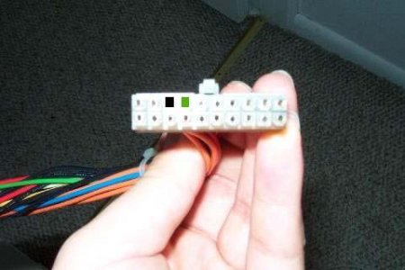
In order to start the ATX unit, you simply need to short-circuit the green and any black wires on the power supply connector (PS-ON and GND pins, respectively, see the figure below).

This is what it looks like in real life:

It also happens that on some power supplies these wires may be of different colors (you understand - the Chinese), so I recommend taking a closer look at which wire you have as the PS-ON output.
Second way
If you don’t have a piece of wiring at hand, then the same steps can be done using a regular paper clip. We close all the same colors of wires.
Read also:
Why can't you turn on a computer power supply without a load?
Now a few precautions.
If you don't do this, the voltage conversion circuit may fail and require expensive repairs. ATX power supply repair, and maybe its complete replacement due to the economic irrationality of repairs.
By the way, it happens that some power supplies simply may not start without load.
The skill of starting a power supply without a computer and motherboard can be useful not only for system managers, but also for ordinary users. When problems appear with your PC, it is important to check the functionality of its individual parts. Any person can cope with this task. How to turn on the power supply?
How to turn on the power supply without a computer (without a motherboard)
Previously, there were power supplies (abbreviated as BP) of the AT standard, which were launched directly. With modern ATX devices, such a trick will not work. To do this, you will need a small wire or an ordinary paper clip to close the contacts on the plug.

Modern computers use the ATX standard. There are two types of connectors for it. The 1st, older one, has 20 pins on the plug, the 2nd - 24. In order to start the power supply, you need to know which contacts to close. Most often this is the green PS_ON pin and the black ground pin.
Note! In some “Chinese” versions of the power supply, the wire colors are mixed up, so it is better to familiarize yourself with the contact diagram (pinout) before starting work.
Step-by-step instruction
So, when you have familiarized yourself with the wiring diagram, you can start starting.
1. If the power supply is in the system unit, disconnect all wires and pull it out.
2. Old 20-pin power supplies are very sensitive, and in no case can they be started without a load. To do this, you need to connect an obscene (but working) hard drive, a cooler, or a primitive garland. The main thing is that the power supply does not run idle, otherwise its service life will be greatly reduced.

Connect something to the power supply to create a load, say a cooler
3. Take a close look at the pin diagram and compare it with your plug. It is necessary to close PS_ON and COM. Since there are several of them, choose the ones that are most comfortable for you.
Observe the pin arrangement on your plug and on the diagram.
4. Make a jumper. This could be a short wire with bare ends or a paper clip.
5. Close the selected contacts.

Close the PS_ON and COM contacts
6.Turn on the power supply.
The fan is noisy - the power supply is working.
Checking the functionality of the power supply is a simple task that an ordinary PC user can handle. All you have to do is follow the instructions carefully.
In the modern world, the development and obsolescence of personal computer components occurs very quickly. At the same time, one of the main components of a PC - the ATX form factor - is practically has not changed its design for the last 15 years.
Consequently, the power supply of both an ultra-modern gaming computer and an old office PC work on the same principle and have common methods for diagnosing faults.
The material presented in this article can be applied to any personal computer power supply with a minimum of nuances.
A typical ATX power supply circuit is shown in the figure. Structurally, it is a classic pulse unit on a TL494 PWM controller, triggered by a PS-ON (Power Switch On) signal from the motherboard. The rest of the time, until the PS-ON pin is pulled to ground, only the Standby Supply with a voltage of +5 V at the output is active.
Let's take a closer look at the structure of the ATX power supply. Its first element is
:

Its task is to convert alternating current from the mains to direct current to power the PWM controller and standby power supply. Structurally, it consists of the following elements:
- Fuse F1 protects the wiring and the power supply itself from overload in the event of a power supply failure, leading to a sharp increase in current consumption and, as a consequence, to a critical increase in temperature that can lead to a fire.
- A protective thermistor is installed in the neutral circuit, which reduces the current surge when the power supply is connected to the network.
- Next, a noise filter is installed, consisting of several chokes ( L1, L2), capacitors ( C1, C2, C3, C4) and counter-wound choke Tr1. The need for such a filter is due to the significant level of interference that the pulse unit transmits to the power supply network - this interference is not only picked up by television and radio receivers, but in some cases can lead to the malfunction of sensitive equipment.
- A diode bridge is installed behind the filter, converting alternating current into pulsating direct current. Ripple is smoothed out by a capacitive-inductive filter.

Standby power supply is a low-power independent pulse converter based on the T11 transistor, which generates pulses through an isolation transformer and a half-wave rectifier on the D24 diode, powering a low-power integrated voltage stabilizer on the 7805 chip. Although this circuit is, as they say, time-tested, its significant drawback is high voltage drop across the 7805 stabilizer, which leads to overheating under heavy load. For this reason, damage in the circuits powered from the standby source can lead to its failure and subsequent inability to turn on the computer.
The basis of the pulse converter is PWM controller. This abbreviation has already been mentioned several times, but has not been deciphered. PWM is pulse width modulation, that is, changing the duration of voltage pulses at their constant amplitude and frequency. The task of the PWM unit, based on a specialized TL494 microcircuit or its functional analogues, is to convert DC voltage into pulses of the appropriate frequency, which, after an isolation transformer, are smoothed by output filters. Voltage stabilization at the output of the pulse converter is carried out by adjusting the duration of the pulses generated by the PWM controller.