Li ion battery controller charging circuit. Li-ion and Li-polymer batteries in our designs. Main types of batteries used
And again a device for homemade ones.
The module allows you to charge Li-Ion batteries (both protected and unprotected) from a USB port using a miniUSB cable.
The printed circuit board is double-sided fiberglass with metallization, the installation is neat. 

Charging is assembled on the basis of a specialized charge controller TP4056.
Real scheme. 
On the battery side, the device does not consume anything and can be left constantly connected to the battery. Short circuit protection at the output - yes (with current limitation 110mA). There is no protection against battery reverse polarity.
The miniUSB power supply is duplicated by nickels on the board. 

The device works like this:
When connecting power without a battery, the red LED lights up and the blue LED blinks periodically.
When you connect a discharged battery, the red LED goes out and the blue LED lights up - the charging process begins. As long as the battery voltage is less than 2.9V, the charging current is limited to 90-100mA. With an increase in voltage above 2.9V, the charge current sharply increases to 800mA with a further smooth increase to the nominal 1000mA.
When the voltage reaches 4.1V, the charging current begins to gradually decrease, then the voltage stabilizes at 4.2V and after the charging current decreases to 105mA, the LEDs begin to switch periodically, indicating the end of the charge, while the charge still continues by switching to the blue LED . Switching occurs in accordance with the hysteresis of the battery voltage control.
The nominal charge current is set by a 1.2 kOhm resistor. If necessary, the current can be reduced by increasing the resistor value according to the controller specification.
R (kOhm) - I (mA)
10 - 130
5 - 250
4 - 300
3 - 400
2 - 580
1.66 - 690
1.5 - 780
1.33 - 900
1.2 - 1000
The final charge voltage is hard-set at 4.2V - i.e. Not every battery will be 100% charged.
Controller specification.
Conclusion: The device is simple and useful for a specific task.
Planning to buy +167 Add to favorites I liked the review +96 +202A lot of ten pieces was purchased to convert the power supply of some devices to li-ion batteries ( They currently use 3AA batteries.), but in the review I will show another option for using this board, which, although it does not use all its capabilities. It’s just that out of these ten pieces, only six will be needed, and buying 6 pieces with protection and a pair without protection turns out to be less profitable.
Based on the TP4056, the charge board with protection for Li-Ion batteries with a current of up to 1A is designed for full charging and protection of batteries ( for example, the popular 18650) with the ability to connect a load. Those. This board can be easily integrated into various devices, such as flashlights, lamps, radios, etc., powered by a built-in lithium battery, and charged without removing it from the device using any USB charger via a microUSB connector. This board is also perfect for repairing burnt-out Li-Ion battery chargers.
And so, a bunch of boards, each in an individual bag ( there is of course less than what was bought)

The scarf looks like this:

You can take a closer look at the installed elements

On the left is a microUSB power input, the power is also duplicated by the + and - pads for soldering.
In the center is a charge controller, Tpower TP4056, above it a pair of LEDs displaying either the charging process (red) or the end of charge (blue), below it is resistor R3, by changing the value of which you can change the battery charge current. TP4056 charges batteries using the CC/CV algorithm and automatically ends the charging process if the charge current drops to 1/10 of the set one.
Table of resistance and charging current ratings, according to the controller specification.
- R (kOhm) - I (mA)
- 1.2 - 1000
- 1.33 - 900
- 1.5 - 780
- 1.66 - 690
- 2 - 580
- 3 - 400
- 4 - 300
- 5 - 250
- 10 - 130
There is nothing on the back of the board, so you can, for example, glue it.

And now the option of using a board for charging and protecting li-ion batteries.
Nowadays, almost all amateur video cameras use 3.7V li-ion batteries as power sources, i.e. 1S. Here is one of the additional batteries purchased for my video camera

I have several of them, produced ( or markings) DSTE model VW-VBK360 with a capacity of 4500 mAh ( not counting the original one, at 1790mAh)

Why do I need so much? Yes, of course, my camera is charged from a power supply with a rating of 5V 2A, and having purchased a USB plug and a suitable connector separately, I can now charge it from power banks ( and this is one of the reasons why I, and not only me, there are so many of them), but it’s just inconvenient to shoot with a camera that also has a wire attached to it. This means that you need to somehow charge the batteries outside the camera.
I have already shown this kind of exercise

Yes, yes, this is it, with an American standard rotating fork

This is how it separates easily

And just like that, a charge and protection board for lithium batteries is implanted into it

And of course, I brought out a couple of LEDs, red - the charging process, green - the end of the battery charge

The second board was installed in a similar way, into a charger from a Sony video camera. Yes, of course, new models of Sony camcorders charge via USB, they even have a non-detachable USB tail ( stupid decision in my opinion). But again, in field conditions, filming with a camera that has a cable from a power bank is less convenient than without it. Yes, and the cable must be long enough, and the longer the cable, the greater its resistance and the greater the losses on it, and reducing the cable resistance by increasing the thickness of the cores, the cable becomes thicker and less flexible, which does not add convenience.
So from such boards for charging and protecting li-ion batteries up to 1A on the TP4056 you can easily make a simple battery charger with your own hands, convert the charger to powered from USB, for example, for charging batteries from a power bank, make repairs charger if necessary.
Everything written in this review can be seen in the video version:
First you need to decide on the terminology.
As such there are no discharge-charge controllers. This is nonsense. There is no point in managing the discharge. The discharge current depends on the load - as much as it needs, it will take as much. The only thing you need to do when discharging is to monitor the voltage on the battery to prevent it from overdischarging. For this purpose they use .
At the same time, separate controllers charge not only exist, but are absolutely necessary for the process of charging li-ion batteries. They set the required current, determine the end of the charge, monitor the temperature, etc. The charge controller is an integral part of any.
Based on my experience, I can say that a charge/discharge controller actually means a circuit for protecting the battery from too deep a discharge and, conversely, overcharging.
In other words, when we talk about a charge/discharge controller, we are talking about the protection built into almost all lithium-ion batteries (PCB or PCM modules). Here she is:
And here they are too: 
Obviously, protection boards are available in various form factors and are assembled using various electronic components. In this article we will look at options for protection circuits for Li-ion batteries (or, if you prefer, discharge/charge controllers).
Charge-discharge controllers
Since this name is so well established in society, we will also use it. Let's start with, perhaps, the most common version on the DW01 (Plus) chip.
DW01-Plus
Such a protective board for li-ion batteries is found in every second mobile phone battery. To get to it, you just need to tear off the self-adhesive with inscriptions that is glued to the battery.

The DW01 chip itself is six-legged, and two field-effect transistors are structurally made in one package in the form of an 8-legged assembly.
Pin 1 and 3 control the discharge protection switches (FET1) and overcharge protection switches (FET2), respectively. Threshold voltages: 2.4 and 4.25 Volts. Pin 2 is a sensor that measures the voltage drop across field-effect transistors, which provides protection against overcurrent. The transition resistance of transistors acts as a measuring shunt, so the response threshold has a very large scatter from product to product.
The whole scheme looks something like this: 
The right microcircuit marked 8205A is the field-effect transistors that act as keys in the circuit.
S-8241 Series
SEIKO has developed specialized chips to protect lithium-ion and lithium-polymer batteries from overdischarge/overcharge. To protect one can, integrated circuits of the S-8241 series are used. 
Overdischarge and overcharge protection switches operate at 2.3V and 4.35V, respectively. Current protection is activated when the voltage drop across FET1-FET2 is equal to 200 mV.
AAT8660 Series
LV51140T
A similar protection scheme for single-cell lithium batteries with protection against overdischarge, overcharge, and excess charge and discharge currents. Implemented using the LV51140T chip. 
Threshold voltages: 2.5 and 4.25 Volts. The second leg of the microcircuit is the input of the overcurrent detector (limit values: 0.2V when discharging and -0.7V when charging). Pin 4 is not used.
R5421N Series
The circuit design is similar to the previous ones. In operating mode, the microcircuit consumes about 3 μA, in blocking mode - about 0.3 μA (letter C in the designation) and 1 μA (letter F in the designation). 
The R5421N series contains several modifications that differ in the magnitude of the response voltage during recharging. Details are given in the table:
SA57608
Another version of the charge/discharge controller, only on the SA57608 chip. 
The voltages at which the microcircuit disconnects the can from external circuits depend on the letter index. For details, see the table:
The SA57608 consumes a fairly large current in sleep mode - about 300 µA, which distinguishes it from the above-mentioned analogues for the worse (where the current consumed is on the order of fractions of a microampere).
LC05111CMT
And finally, we offer an interesting solution from one of the world leaders in the production of electronic components On Semiconductor - a charge-discharge controller on the LC05111CMT chip. 
The solution is interesting in that the key MOSFETs are built into the microcircuit itself, so all that remains of the attached elements are a couple of resistors and one capacitor.
The transition resistance of the built-in transistors is ~11 milliohms (0.011 Ohms). The maximum charge/discharge current is 10A. The maximum voltage between terminals S1 and S2 is 24 Volts (this is important when combining batteries into batteries).
The microcircuit is available in the WDFN6 2.6x4.0, 0.65P, Dual Flag package.
The circuit, as expected, provides protection against overcharge/discharge, overload current, and overcharging current.
Charge controllers and protection circuits - what's the difference?
It is important to understand that the protection module and charge controllers are not the same thing. Yes, their functions overlap to some extent, but calling the protection module built into the battery a charge controller would be a mistake. Now I’ll explain what the difference is.
The most important role of any charge controller is to implement the correct charge profile (usually CC/CV - constant current/constant voltage). That is, the charge controller must be able to limit the charging current at a given level, thereby controlling the amount of energy “poured” into the battery per unit of time. Excess energy is released in the form of heat, so any charge controller gets quite hot during operation.
For this reason, charge controllers are never built into the battery (unlike protection boards). The controllers are simply part of a proper charger and nothing more.
In addition, not a single protection board (or protection module, whatever you want to call it) is capable of limiting the charge current. The board only controls the voltage on the bank itself and if it goes beyond preset limits, it opens the output switches, thereby disconnecting the bank from outside world. By the way, short circuit protection also works on the same principle - during a short circuit, the voltage on the bank drops sharply and the deep discharge protection circuit is triggered.
Confusion between the protection circuits for lithium batteries and charge controllers arose due to the similarity of the response threshold (~4.2V). Only in the case of a protection module is the can completely disconnected from the external terminals, and in the case of a charge controller is it switched to a voltage stabilization mode and a gradual reduction in the charging current.

In this article we will talk about the Li-Ion charge controller on the MCP73833.
Picture 1.
Previous experience
Up to this point I have been using LT4054 controllers, and to be honest, I was pleased with them:
It allowed charging compact Li-Pol batteries with a capacity of up to 3000 mAh
Was ultra-compact: sot23-5
Had a battery charging indicator
It has a bunch of protections, which makes it a practically indestructible chip

Figure 2.
An additional advantage is that before I started doing anything with it, I bought 50 of them, at a very modest price.
I identified shortcomings in the work, and, frankly speaking, they put me in a partial stupor:
The maximum declared current is 1A, I thought. But already at 300 mA during charging, the chip warms up to 110 * C, even in the presence of large radiator polygons and a radiator attached to the plastic surface of the chip.
When the thermal protection is turned on, a comparator apparently triggers, which quickly resets the current. As a result, the microcircuit turns into a generator, which kills the battery. This way I killed 2 batteries until I figured out what was wrong with the oscilloscope.
In view of the above, I got a problem with the device charging time of about 10 hours. Of course, this greatly dissatisfied me and the consumers of my electronics, but what can I do: everyone wanted to increase the service life with the same parameters of the device, and sometimes they consume a lot.
In this regard, I started looking for a controller that would have the best parameters and heat dissipation capabilities, and my choice so far has settled on the MCP73833, mainly due to the fact that my friend had these controllers in stock, and I whistled a couple of pieces quickly (faster than him) soldered the prototype and carried out the tests I needed.
A little about the controller itself.
Let me not engage in a complete and thorough translation of the datasheet (although this is useful), but quickly and simply tell you what I looked at first in this controller and whether I liked it or not.
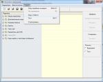
1. The general switching diagram is what catches your eye from the beginning. It is easy to notice that, with the exception of the indication (which you don’t have to do), the harness consists of only 4 parts. They include two filter capacitors, a resistor for programming the battery charge current, and a 10k thermistor to control overheating of the Li-Ion battery. This circuit is shown in Figure 3. This is definitely cool.

Figure 3. Connection diagram MCP73833
2. She is much better with heat. This can be seen even from the connection diagram, since identical legs are visible that can be used for heat removal. In addition to this, looking at the fact that the chip is available in msop-10 and DFN-10 packages, which are larger in surface area than sot23-5. Moreover, in the DFN-10 case there is a special polygon, which can and should be used as a heat sink to a large surface. If you don’t believe me, then look at Figure 4 for yourself. It shows the pinouts of the legs of the DFN-10 case and the manufacturer’s recommended PCB layout, with heat dissipation using a polygon.

Figure 4.
3. The presence of a 10k thermistor. Of course, in most cases I will not use it, since I am sure that I will not overheat the battery, but: there are tasks in which I mean a full charge of the battery in just 30 minutes of operation from the power supply. In such cases, the battery itself may overheat.
4. A rather complex battery charging indication system. As I understood and tried: there is 1 LED responsible for whether power is supplied from the charging power supply. In theory, the thing is not so necessary, but: I had cases when I broke the connector and the controller simply did not receive 5V at the input. In such cases, it was immediately clear what was wrong. An extremely useful feature for developers. For consumers, it is easily replaced by simply an LED along the 5V input line, installed with a current-limiting resistor.
5. The remaining two LEDs are broken during the charging stage. This allows you to unload the MK (if you do not need, for example, to show the battery charge on the display) in terms of processing the charge on the battery during charging (indication whether it is charged or not).
6. Programming the charge current over a wide range. Personally, I tried to increase the charging current to 1A on the board shown in Figure 1, and at around 890mA the board went into thermal protection in stable mode. As people around say, with large ranges they perfectly pulled out 2A from this controller, and according to the technical description, the maximum charge current is 3A, but I have a number of doubts related to the thermal load on the microcircuit.
7. If you believe the datasheet, then this microcircuit has: Low-Dropout Linear Regulator Mode - a mode of reduced input voltage. In these modes, using a DC-DC converter, you can carefully reduce the voltage at the input of the microcircuit during the start of charging to reduce its heat generation. Personally, I tried to reduce the voltage, and the heat logically became less, but at least 0.3-0.4V should drop on this microcircuit so that it can comfortably charge the battery. Purely technically, I’m going to make a small module that does this automatically, but I don’t have the money or time for this, so I happily ask everyone who is interested to email me. If there are a few more people, we will release such a thing on our website.
8. I didn’t like that the body was very small. Soldering it without a hair dryer (DFN-10) is difficult, and it won’t work out well, no matter how you look at it. It's better with msop-10, but it takes a lot of time for beginners to learn how to solder it.
9. I didn’t like that this controller does not have a built-in BMS (battery protection from rapid charge/discharge and a number of other problems). But more expensive controllers from TI have such things.
10. I liked the price. These controllers are not expensive.
What's next?
And then I’m going to implement this chip into my various device ideas. For example, it is now already produced at the factory trial version development board based on STM32F103RCT6 and 18650 batteries. I already have a development board for this controller, which has proven itself very well, and I want to complement it with a portable version so that I can take my work project with me and not think about power and searching for a socket into which to insert the power supply.
I will also use it in all solutions that require charging currents of more than 300mA.
I hope you will be able to use this useful and simple chip in your devices.
If you are at all interested in battery power, here is my personal video about battery power for devices.
All radio amateurs are very familiar with charge boards for one can of li-ion batteries. It is in great demand due to its low price and good output parameters.


Used to charge the previously mentioned batteries at a voltage of 5 Volts. Such scarves are widely used in homemade designs with an autonomous power source in the form of lithium-ion batteries.
These controllers are produced in two versions - with and without protection. Those with protection are a little expensive.
Protection performs several functions
1) Disconnects the battery during deep discharge, overcharging, overload and short circuit.

Today we will check this scarf in great detail and understand whether the parameters promised by the manufacturer correspond to the real ones, and we will also arrange other tests, let's go.
The board parameters are shown below
And these are the circuits, the top one with protection, the bottom one without
Under a microscope it is noticeable that the board is of very good quality. Double-sided glass fiber laminate, no “couples”, silk-screen printing is present, all inputs and outputs are marked, it is not possible to mix up the connection if you are careful.

The microcircuit can provide a maximum charge current of around 1 Ampere; this current can be changed by selecting the resistor Rx (highlighted in red).
And this is a plate of the output current depending on the resistance of the previously indicated resistor.
The microcircuit sets the final charging voltage (about 4.2 Volts) and limits the charging current. There are two LEDs on the board, red and blue (colors may be different). The first lights up during charging, the second when the battery is fully charged.
There is a Micro USB connector that supplies 5 volts.
First test.
Let's check the output voltage to which the battery will be charged, it should be from 4.1 to 4.2V

That's right, no complaints.
Second test
Let's check the output current, on these boards the maximum current is set by default, and this is about 1A.
We will load the output of the board until the protection is triggered, thereby simulating high consumption at the input or a discharged battery.
The maximum current is close to the declared one, let's move on.
Test 3
Connected to the battery location laboratory block power supply on which the voltage is pre-set around 4 volts. We reduce the voltage until the protection turns off the battery, the multimeter displays the output voltage.

As you can see, at 2.4-2.5 volts the output voltage disappeared, that is, the protection is working. But this voltage is below critical, I think 2.8 Volts would be just right, in general, I do not advise discharging the battery to such an extent that the protection will work.
Test 4
Checking the protection current.
For these purposes, an electronic load was used; we gradually increased the current.
The protection operates at currents of about 3.5 Amps (clearly visible in the video)
Among the shortcomings, I will only note that the microcircuit heats up ungodly and even a heat-intensive board does not help. By the way, the microcircuit itself has a substrate for effective heat transfer and this substrate is soldered to the board, the latter plays the role of a heat sink.


I don’t think there’s anything to add, we saw everything perfectly, the board is excellent budget option, when it comes to a charge controller for one can of small-capacity Li-Ion battery.
I think this is one of the most successful developments of Chinese engineers, which is available to everyone due to its insignificant price.
Happy Stay!